Advertisement
Quick Links
Advertisement

Related Manuals for Subzero BI-36U/O


Summary of Contents for Subzero BI-36U/O
- Page 1 800.222.7820 Service Manual Installation Information...
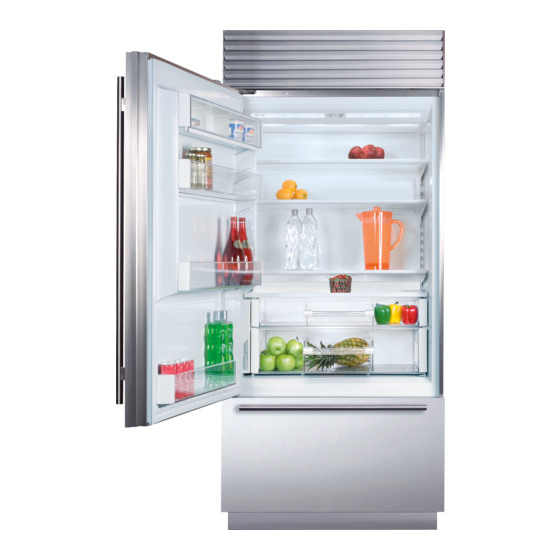
- Page 2 General Information Built-In (BI) Series Built-In (BI) Series (SWS #4250000) (SWS #4250000) MODEL DESCRIPTION BI-36U/O Built-In Series, 36” Wide, Over/Under, Overlay Door Trim (No Handles), Panel Grille (Standard) BI-36U/S Built-In Series, 36” Wide, Over/Under, Classic Stainless Steel Wrapped Doors, Stainless Steel Grille (Standard)
-
Page 3: General Information
General Information Built-In (BI) Series Built-In (BI) Series (SWS #4250000) (SWS #4250000) MODEL DESCRIPTION BI-36S/O Built-In Series, 36” Wide, Side-by-Side, Overlay Door Trim (No Handles), Panel Grille (Standard) BI-36S/S Built-In Series, 36” Wide, Side-by-Side, Classic Stainless Steel Wrapped Doors, Stainless Steel Grille (Standard) NOTE: Framed Design application is only avail- able with use of Sales Accessory Handles and grille panel. - Page 4 General Information Built-In (BI) Series Built-In (BI) Series (SWS #4250000) (SWS #4250000) MODEL DESCRIPTION BI-42SID/O Built-In Series, 42” Wide, Side-by-Side, Internal Ice/Water Dispenser, Overlay Door Trim (No Handles), Panel Grille (Standard) DISPENSER BI-42SID/S Built-In Series, 42” Wide, Side-by-Side, Internal Ice/Water Dispenser, Classic Stainless Steel Wrapped Doors, Louver Grille (Standard) NOTE: Framed Design application is only avail- able with use of Sales Accessory Handles and...
- Page 5 General Information Built-In (BI) Series Built-In (BI) Series (SWS #4250000) (SWS #4250000) MODEL DESCRIPTION BI-48SD/O Built-In Series, 48” Wide, Side-by-Side, Ice/Water Dispenser, Overlay Door Trim (No Handles), Panel Grille (Standard) BI-48SD/S Built-In Series, 48” Wide, Side-by-Side, Ice/Water Dispenser, Classic Stainless Steel Wrapped Doors, Louver Grille (Standard) NOTE: Framed Design application is only avail- able with use of Sales Accessory Handles and...
-
Page 6: Installation Considerations
Installation Information Built-In (BI) Series Built-In (BI) Series (SWS #4250000) (SWS #4250000) INSTALLATION CONSIDERATIONS This section uses some of the information in the BI Series Installation Guide to address common installation issues seen by Service Technicians. Improper installation, though not a valid service issue, has the potential to lead to a call for service. - Page 7 Installation Information Built-In (BI) Series Built-In (BI) Series (SWS #4250000) (SWS #4250000) Finished Rough Opening Specifications (30”, 36” and 42” Over / Under Models) 6" 18" (457) (152) TOP VIEW * ANTI-TIP BRACKET MUST NOT " INTERFERE WITH WATER LINE. (13) WATER LINE REFER TO INSTALLATION INSTRUCTIONS FOR COMPLETE 24"...
- Page 8 Installation Information Built-In (BI) Series Built-In (BI) Series (SWS #4250000) (SWS #4250000) Finished Rough Opening Specifications (36” All Refrigerator and All Freezer Models) 6" 18" (457) (152) TOP VIEW * ANTI-TIP BRACKET MUST NOT " INTERFERE WITH WATER LINE. (13) WATER LINE REFER TO INSTALLATION INSTRUCTIONS FOR COMPLETE 24"...
- Page 9 Installation Information Built-In (BI) Series Built-In (BI) Series (SWS #4250000) (SWS #4250000) Finished Rough Opening Specifications (36”, 42” and 48” Side-by-Side Models) 6" 18" (457) (152) TOP VIEW * ANTI-TIP BRACKET MUST NOT " INTERFERE WITH WATER LINE. (13) WATER LINE REFER TO INSTALLATION INSTRUCTIONS FOR COMPLETE 24"...
- Page 10 Installation Information Built-In (BI) Series Built-In (BI) Series (SWS #4250000) (SWS #4250000) Anti-Tip Bracket Installation THE UNIT COULD TIP FORWARD UNDER CERTAIN LOAD CONDITIONS. FAILURE TO INSTALL BOTH ANTI-TIP BRACKETS AND EXTEND LEVELERS TO FLOOR ACCORDING TO INSTALLATION MANUAL COULD RESULT IN SERIOUS INJURY OR DEATH. IMPORTANT NOTE: Placement of the two anti-tip brackets is critical.
- Page 11 Installation Information Built-In (BI) Series Built-In (BI) Series (SWS #4250000) (SWS #4250000) Flush Inset Installation Procedure: The two anti-tip brackets must be located 24''(610 mm) back from front of rough opening and a minimum of 4” (102 mm) from sides of rough opening. This will ensure that ant- tip brackets properly engage anti-tip bar at back of unit.
- Page 12 Installation Information Built-In (BI) Series Built-In (BI) Series (SWS #4250000) (SWS #4250000) Electrical Requirements Plumbing Requirements A 115 V AC, 60 Hz, 15 amp circuit breaker and electri- All Built-In models with an automatic ice maker are also cal supply are required. A separate circuit, servicing equipped with a factory installed, microbiological water only this appliance, is required.
- Page 13 Installation Information Built-In (BI) Series Built-In (BI) Series (SWS #4250000) (SWS #4250000) Water Line Connections Water Filtration System Approximately 3' (914mm) of 1/4" plastic tubing is con- The water filtration system of Sub-Zero built-in models nected to the unit with a preassembled 1/4" compres- supplies filtered water to the ice maker and water dis- sion connection at the end.
- Page 14 Installation Information Built-In (BI) Series Built-In (BI) Series (SWS #4250000) (SWS #4250000) Leveling the Unit Door Adjustments Once the unit is in position, the front leveling legs must The doors on the Built-In Series side-by-side and single be extended down to the floor by turning them clock- door models can be adjusted in three ways: up and wise.
-
Page 15: Mounting Bolts
Installation Information Built-In (BI) Series Built-In (BI) Series (SWS #4250000) (SWS #4250000) Side to Side and In and Out Adjustment Procedure: 90-Degree Door Stop IMPORTANT NOTE: Side to side and in and out The doors on all Built-in Series units open to 110- adjustments only affect the top of the door. - Page 16 Installation Information Built-In (BI) Series Built-In (BI) Series (SWS #4250000) (SWS #4250000) Door and Drawer Panels Regardless of the installation application, it may be necessary to remove and/or install a door or drawer panel. To do this, the handle or handle-side trim will need to be removed first. The handle or handle-side trim is attached to the door or drawer with screws, and these screws are concealed by a screw cover.
- Page 17 Installation Information Built-In (BI) Series Built-In (BI) Series (SWS #4250000) (SWS #4250000) Drawer Handle / Handle-Side Trim Removal Procedure: 1. At the back right-hand side of the drawer handle or handle-side trim, insert a flat blade screwdriver into the notch in the screw cover and pry the cover away form the handle or handle-side trim, disengaging the screw cover from the clips (See Figures 2-17A and 2-17B).
- Page 18 Installation Information Built-In (BI) Series Built-In (BI) Series (SWS #4250000) (SWS #4250000) Glasswell - Door Dispenser Assembly If attempting to remove and/or install a door panel on the refrigerator door of a door dispenser model, note that the procedure is the same as that listed on the previous pages. However, the dispenser control panel and glasswell bezel will also need to be removed.
Need help?
Do you have a question about the BI-36U/O and is the answer not in the manual?
Questions and answers