Advertisement
Quick Links
Advertisement

Related Manuals for Custom Crimp D100 SERIES


Summary of Contents for Custom Crimp D100 SERIES
- Page 1 D100 SERIES HYDRAULIC HOSE CRIMPER OPERATORS MANUAL...
-
Page 2: Models Covered
Page MODELS COVERED This manual is applicable to different versions of the D_100_ Series Crimpers. A “Standard”, “Metric” and “DC” micrometer is available on different models. Crimping, calibration and repair procedures are similar for all models. See specific instructions and parts breakdown for the model in question D100P SERIES CRIMPER D100H SERIES CRIMPER VALPOWER PUMP... -
Page 3: Safety Precautions
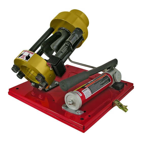
COMPONENT PART IDENTIFICATION Page MICRO-CRIMP ADJUSTER REMOVABLE CALIBRATION PUSHER ADJUSTMENT SCREW POWER SOURCE MANUAL UNIT SHOWN COMPRESSION RING “DC” STANDARD METRIC STANDARD DOUBLE ANGLE DIE SET DIE SET AVAILABLE MICRO-CRIMP MICROMETERS SAFETY PRECAUTIONS READ INSTRUCTIONS AND IDENTIFY ALL COMPONENT PARTS BEFORE USING CRIMPER. - Page 4 • Check crimper calibration prior to initial operation • Seat the Pressure Plate (flat plate) in the base of the crimper • Place any D100 series die set on top of the Pressure Plate making certain that the die set is firmly seated against the Pressure Plate.
-
Page 5: Calibration Instructions
CALIBRATION INSTRUCTIONS Page • Place the Pressure Plate, any D100 Series Standard Die Set and the Compression Ring in the crimper in the order shown. Do Not use Double Angle Components • Set the Micro-Crimp Adjuster as follows: Standard Micrometer: “100”... - Page 6 CRIMPING WITH STANDARD DIES Page • Place the flat pressure plate in the bottom flange and select the correct die set for the combination of hose and fitting to be crimped. Refer to the hose and fitting manufacturer’s recommendation for the correct die set to use. •...
- Page 7 CRIMPING WITH A DOUBLE ANGLE DIE Page • The Double Angle Dies are special purpose dies designed to double the crimping force thus allowing larger fittings to be crimped with less vertical force. The limitation, however, is that they must crimp to a near fully closed position and therefore a given die set can crimp only limited range above the diameter shown on the die ring.
- Page 8 COMPONENT IDENTIFICATION Page...
- Page 9 COMPONENT IDENTIFICATION Page...
- Page 10 COMPONENT IDENTIFICATION Page...
-
Page 11: Component Identification
COMPONENT IDENTIFICATION Page 35-Ton Head Sub-Assembly (101209) ITEM PART NUMBER DESCRIPTION 103122 35-Ton Cylinder/Flange 100329 Strain Rod - 8 1/2" 100325 Bottom Flange 750SPCL 3/4 Flat Washer - Special 95462A538 3/4-10 Hex Nut... - Page 12 COMPONENT IDENTIFICATION Page 35 Ton Cylinder / Flange Assembly (103122) ITEM PART NUMBER DESCRIPTION 102511 Cylinder Body 101515 Cylinder Piston 030D90 030 Disogrin O-Ring 100689 Cylinder Piston Cap 91251A540 1/4-20 X 3/4 SHCS 101282 Cylinder Spring 101516 Spring Plug 210D90 210 Disogrin O-Ring TP032 T-Seal...
Need help?
Do you have a question about the D100 SERIES and is the answer not in the manual?
Questions and answers