Table of Contents
Advertisement
Quick Links
Advertisement
Table of Contents

Related Manuals for Custom Crimp CC60


Summary of Contents for Custom Crimp CC60
- Page 1 CC60 CRIMPER OPERATORS MANUAL WITH ACT CONTROLLER...
-
Page 2: Table Of Contents
DIE SET UP AND INSTALLATION ----------------------------------------------------------------------------------------13 HYDRAULIC DIE INSTALLATION ----------------------------------------------------------------------------------------14 AccuStopTM COUPLING STOP-------------------------------------------------------------------------------------------15 INITIAL SETUP AND MAINTENANCE -----------------------------------------------------------------------------------16 TROUBLESHOOTING --------------------------------------------------------------------------------------------------------17 PLC RESET/RELAY REPLACEMENT------------------------------------------------------------------------------------18 COMPONENT PARTS BREAKDOWN -----------------------------------------------------------------------------------19 For Parts and Service, Contact: Custom Machining Services, Inc. Valparaiso, In 46383 (219) 462-6128 CC60 Manual-ACT Controller(Rev 10/16/2008) -
Page 3: Component Parts Identification
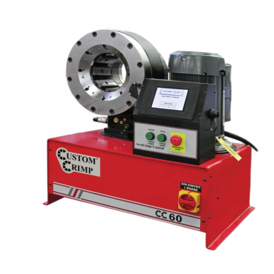
CRIMPER COMPONENT PARTS CRIMPER HEAD MOTOR ROTATION CONTROLLER INTERMEDIATE DIES OIL FILLER CAP MASTER POWER SWITCH OIL LEVEL SIGHT GLASS FOOT SWITCH PLUG IN PORT FOOT SWITCH TANK DRAIN AND OIL COOLER PORTS... -
Page 4: Specifications And Initial Set
CRIMPER SPECIFICATIONS AND SET UP SPECIFICATIONS: MAX HEAD OPENING W/O DIES ------------------------------------------------------------------------182 MM (7.17 IN) MASTER DIE INSIDE DIAMETER -----------------------------------------------------------------------145 MM (5.71 IN) MAXIMUM DIE OPENING ----------------------------------------------------------DIE CLOSED DIAMETER + 60 MM CRIMPER SIZE ---------------------------------------------------------------29 IN LONG X 20 IN DEEP X 32 IN HIGH WEIGHT ----------------------------------------------------------------------------------------------------------573 LB (269 KG) ELECTRICAL REQUIREMENTS ---------------------------------------------------220 VOLT 3 PHASE (STANDARD) ----------------------------------------------------------------------------------------------- 440 VOLT 3 PHASE (OPTIONAL) -
Page 5: Act Tm Control Panel Operation
AccuCrimp ACT CONTROL PANEL Patent No: 7,383,709 EMERGENCY STOP MANUAL MODE FUNCTION: OPEN DIES AUTO MODE FUNCTION: CYCLE STOP MANUAL MODE FUNCTION: CLOSE DIES AUTO MODE FUNCTION: CYCLE START NOTE: MANUAL MODE IF THE CRIMPER IS IN , THE GREEN OPEN/CLOSE BUTTONS WILL OPEN AND CLOSE THE CRIMPER HEAD. - Page 6 CONTROLLER QUICK START Patent No: 7,383,709 While the ACT crimper has the ability to perform a number of fully automatic functions, manual operation is also possible. To make a manual crimp, two numbers are needed: The closed diameter of the die (in either inches or The fi...
- Page 7 HOW TO MAKE MINOR CORRECTIONS • Due to variations in hose and fi tting tolerances a minor crimp adjustment may be required if the measured diameter of the fi nal crimp is not within the hose and fi tting manufacturer’s specifi...
- Page 8 HOW TO ADD A SAVED DIE Up to 50 different dies can be saved in the computer memory. These dies can be recalled in the set up process eliminating the need to re-enter the die size each time. To enter a saved die: •...
- Page 9 HOW TO ADD A SAVED CRIMP • Adjust the die diameter and crimp diameter as required and place the crimper in MANUAL mode. • Press SAVE • Select a location (1-100) and press EDIT • Enter a description (up to 12 characters) •...
- Page 10 The minimum retraction diameters are: CC38 - Crimp Diameter plus 2 mm CC4-50 - Crimp Diameter plus 2 mm CC60 - Crimp Diameter plus 3 mm • Pressing the FULL AUTO button will toggle the crimper into SEMI-AUTO mode. In SEMI-AUTO mode, pressing the FOOT SWITCH or the CLOSE button will close the crimper head and releasing it will cause the head to stop closing.
- Page 11 ADJUST CRIMP COUNT If a production operation is interrupted for some reason, it is possible to reset the counter to where the operation was at the point of interruption. • Press the Adjust Count button from the auto crimp screen. •...
- Page 12 ADDITIONAL FEATURES Pre-Loaded Crimp Specifications In addition to the ability to store up to 50 user entered dies and 100 user entered crimp settings, the ACTTM Controller has the capability of accepting pre loaded manufacturer’s crimp specifi- cations. CustomCrimp® does not maintain these specifications as they are proprietary to the individual hose and fitting manu- facturer.
-
Page 13: Die Set Up And Installation
Die to the Master Die. The numbers stamped on the face of the die should face the operator. Note that on the CC60, the master dies must be slightly closed in order to completely insert the die removal tool. Mount all 8 dies in a similar manner. -
Page 14: Hydraulic Die Installation
HYDRAULIC DIE INSTALLATION Install Intermediate Adapter Dies as shown previously making certain that the Intermediate Adapter Die I.D. matches the Hydraulic Die O.D. Remove the Hydraulic Dies from their holder with the magnetic die inser- tion tool as shown. The die size stamped on the face of the die should face toward the opera- Align the studs of the Hydraulic Dies with the holes in the Adapter Dies and with the crimper in manual mode SLOWLY close the crimper head on the die set. -
Page 15: Accustoptm Coupling Stop
AccuStop COUPLING STOP (OPTIONAL) Coupling Stop The optional AccuStop coupling stop elimi- nates guesswork allowing the operator to visually observe exactly where the crimp will be Coupling Stop positioned on the fi tting without the need for trial Clamp and error and product scrap due to poor crimp positioning. -
Page 16: Initial Setup And Maintenance
INITIAL SET UP & MAINTENANCE INITIAL SET UP & MAINTENANCE Do not lift the machine by the crimper head. Lift with a fork lift under the tank. Mount the crimper on a sturdy surface Electrical Requirements: 220 Volt 3 Phase Current (Standard) 440 Volt 3 Phase Current (Optional) DO NOT RUN CRIMPER ON AN EXTENSION CORD Check to be certain that the motor rotates in the direction of the arrow... -
Page 17: Troubleshooting
TROUBLESHOOTING PROBLEM: CRIMPER WILL NOT RUN AT ALL • Check the E-Stop switch to be certain that it is not depressed. A slight twist is required to release switch after it has been depressed. • PLC (Programmable Logic Control) must be reset. See instructions on the following page. PROBLEM: CRIMPER RUNS BUT IS SLOW OR NON-FUNCTIONAL •... -
Page 18: Plc Reset/Relay Replacement
PLC RESET/RELAY REPLACEMENT Electrical Panel (Front Cover Removed) Programmable Logic Controller (PLC) Motor Relay Dies Open Relay Dies Close Relay The PLC (Programmable Logic Controller) requires a relatively constant source of electrical power. Power surges, outages or drops in power can cause the PLC to lose its settings. This may result in missing or misplaced information on the controller screen. -
Page 19: Component Parts Breakdown
COMPONENT PARTS BREAKDOWN 10 11 Touch Panel Housing Assembly (102633) ITEM PART NUMBER DESCRIPTION 69915K55 Cable Strain Relief 9600K24 Grommet - 1/4" 9600K11 Grommet - 1/8" E22PB3A Pushbutton Switch E22LLB2B/E22B1 Emergency Stop Switch 502-N-111 Foot Pedal Jack W/Nut 69915K57 Cable Strain Relief 90935A240 #10 Sheet Metal Screw PX0842/A... - Page 20 COMPONENT PARTS BREAKDOWN 40 41 DETAIL A 21 22 23 34 35...
- Page 21 COMPONENT PARTS BREAKDOWN Crimper Assembly - CC38 (101547) / CC4-50 (101832) / CC60 (101551) ITEM PART NUMBER DESCRIPTION 102618-WELD CC Crimper Reservoir 103049 Sight Glass 4534K43 3/8-18 NPTF Hex Socket Pipe Plug 103048 Venter Filler Cap 102618-03 CC Reservoir Top Plate...
- Page 22 COMPONENT PARTS BREAKDOWN CC Motor and Pump Assembly (101714) ITEM PART NUMBER DESCRIPTION 101541 5 HP 1800 RPM Motor 101540 7.5 HP 1800 RPM Motor 102994 10 HP 1800 RPM Motor 101539 Motor Mounting Flange 91101A033 1/2 Lock Washer 92865A714 1/2-13 x 1 1/4"...
- Page 23 PARTS BREAKDOWN COMPONENT PARTS BREAKDOWN OPTIONAL Crimper Table Assembly (101755) Description Item Part Number 101244 Die Panel 101246 End Panel 90108A030 5/16 Flat Washer 91102A030 5/16 Lock Washer 92865A581 5/16-18 X 1 Hex Bolt 95462A030 5/16-18 Hex Nut Crimper Table Top 101754 101242 99MM Die Holder...
- Page 24 ® CustomCrimp Custom Machining Services, Inc. 326 N. County Rd 400 East Valparaiso, IN 46383 Ph: (219) 462-6128 Fax: (219) 464-2773...
Need help?
Do you have a question about the CC60 and is the answer not in the manual?
Questions and answers