Table of Contents
Advertisement
Advertisement
Table of Contents

Related Manuals for Vernacare Vortex


Summary of Contents for Vernacare Vortex
- Page 1 Issue No: 2...
- Page 2 Technical Manual (Version 1.4) 230 volt single phase machine Vernacare MODEL NO. Amps/Hz Vortex 3.2 @ 50 SERIAL NO. PHASE DATE VOLTS Read relevant manual prior to installation, use or repair of this machine 110 volt single phase machine Vernacare MODEL NO.
- Page 3 Declare that this declaration has been issued under the sole responsibility of the manufacturer. The object of the declaration is in conformity with the relevant Union harmonisation PRODUCT Vernacare Vortex / Vortex + Macerator DIRECTIVE EC Directive 2014/30/EU EC Directive 2006/42/EC...
- Page 4 6. Extended warranties are available. Contact Vernacare for further details. Conditions of warranty 1. The Vortex must be installed to the instructions provided in this technical manual. 2. The Vortex must be commissioned by a person authorised by Vernacare, failure to do so may invalidate the warranty.
-
Page 5: Table Of Contents
Important Information Failure to comply with the instructions & recommendations contained within this manual may impair the safe operation and reliability of the Vernacare Vortex. Vernagroup Ltd, operate a policy of continuous improvement. Whilst every effort is made to ensure that the information contained within this manual is correct, we reserve the right... -
Page 6: Specifications
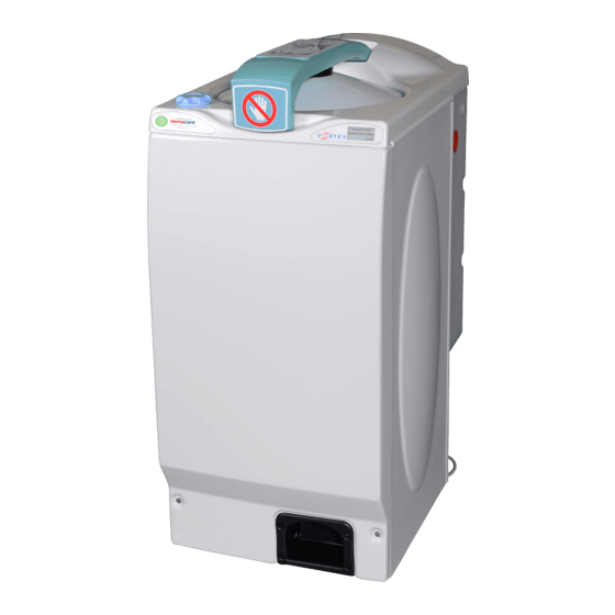
The dimensions of the “Vernacare Vortex” are shown on page 9 (Figure 1) 1.3 Handling The weight of the “Vernacare Vortex” complete with pallet and packaging is 83 kg (machine only 72 kg). The “Vernacare Vortex” should be moved to the point of installation by fork, pallet or sack truck whilst still attached to the pallet provided. - Page 7 A 1 1/4 inch/32mm tank connector is supplied, which should be used to connect the water tank warning pipe to a separate drain line, according to the relevant water regulations. A standard warning pipe installation kit is available. Contact Vernacare Customer Care Department for details.
- Page 8 Figure 1 – Dimensions of the Vernacare Vortex...
-
Page 9: Installation / Commissioning
Ensure that adequate space is maintained at each side of the Macerator to allow for access. Vernacare recommend a gap of 6” - 8” (150 - 200mm) per side and 4” - 5” (100 - 125mm) away from the wall at the back. - Page 10 For installations with dirty water supplies it is recommended that an in-line filter is fitted. 2.2.2 Drain connection The “Vernacare Vortex” is fitted with a 2 inch/50mm ‘P’ Trap. In order to connect to the drain, it is necessary to cut a minimal clearance hole in the plastic drain access cover located at the rear of the machine below the water tank.
- Page 11 2.2.3 Overflow - Warning Pipe The Vortex Is supplied with a 32mm (1 ¼“) tank connector which should be installed using one of the predrilled holes in either the Left Hand side or Right Hand side of the water tank.
- Page 12 2.3.2 Back-up generator tests / mains electrical supply surges. Damage to internal electrical components of the Vortex macerator can occur as a result of voltage surges / spikes occurring In the electrical supply to the machine. The likelihood of such damage occurring is increased when frequent testing of back-up electrical supplies are carried out.
- Page 13 2.7 Display screen icons and warning messages – explanations RUNNING The machine has been started and is running through its cycle. The machine has finished the cycle and is ready to open. BLOCKED BLADES The motor invertor has defaulted to overload due to a blockage of the machine cutter blades.
- Page 14 2.7.1 Cycle Counter At the end of each cycle the LCD screen will briefly display the TOTAL cycle count for the machine and also the SERVICE count which is the number of cycles since the machine was last serviced. The TOTAL cycle display counts every machine cycle and is not resettable (unless the machine is reprogramed).
-
Page 15: General Description
General description The “Vernacare Vortex” macerator is designed to operate within a 2-minute cycle using 25 litres +/-10% of water. The machine can dispose of up to four ‘Vernacare” disposable pulp products, at one time. The products are placed within the hopper; the lid is closed and secured by the handle catch. - Page 16 The display will indicate `End`. The Vortex will remain in this condition with the lid locked until the foot sensor is operated. When the infra red beam is broken by the insertion of the operator’s foot into the foot well at the bottom front of the machine, the interlock pin is withdrawn from the lid catch and the lid springs to the open position.
-
Page 17: Outer Casing
4 Outer Casing Figure 2 - Outer Casing PART DESCRIPTION KIT NUMBER ITEM NUMBER* Front Cover Kit 9207014 Front Cover 9200531 Foot Sensor Housing 9200531 M6 x 20 Panel Screw x2 9750023 9200532 RH Side Panel 9200533 LH Side Panel 9207013 Deodoriser Cap Kit Deodoriser Tank Cap... -
Page 18: Motor Assembly
9752027 Barbed Fitting 9750100 Vortex Motor Cable 9200693 Cutter Motor Adaptor (x1) 9200402 Mechanical Seal (x1) 9753005 9207006 Vortex Mechanical Seal Kit (1.6) Mechanical Seal 9753005 V Seal 9753000 M8 x 50 H.H.S.S 9750006 9207015 Vortex Blade Kit Top Cutter Blade... -
Page 19: Drain Valve Assembly
6 Drain Valve Assembly Figure 4 - Diaphragm Valve and Ancillary components PART DESCRIPTION KIT NUMBER ITEM NUMBER Diaphragm and Spring Kit 9207012 Diaphragm 9200304 Diaphragm Spring 9200333 Retaining Pin 9750085 9207016 Diaphragm Fastening Kit Grub Screw x8 9200326 Three Lobed Nut x 8 9200327 9200724 Water Inlet/Outlet Solenoid Value... -
Page 20: Lid Arm Assembly
7 Lid Arm Assembly Figure 5 – Lid Arm Assembly... - Page 21 D5 Plain Washer x4 9750011 1.20 Lid Arm Label 9200160 1.21 Arm Hinge Shaft x2 9200113 1.22 Damper 9200126 1.23 Arm Spring 9200125 1.24 Hinge Block x2 9200114 Vortex Latch Kit 9207011 Magnet 9200119 Latch 9200157 Locking Block Screw x2 9200120...
-
Page 22: Top Cover Assembly
8 Top Cover Assembly Figure 6 – Top Cover Assembly PART DESCRIPTION KIT NUMBER ITEM NUMBER* Top Cover Assembly Kit 9207002 Top Cover 9200158 Lid Seal 9200159 Lid Seal Clip 9200152 Start Switch Keypad 9200534 Display Screen Not Include in kit 9200819 Display Membrane 9200535... -
Page 23: Lid Interlock Assembly
Interlock Interface Cable Kit 9207018 Interlock Actuator (with cable) 9207017 Interlock Assembly Kit Spring Pin 9200689 Interlock Pin/Pin Shaft 9200687 Interlock Guide Bush 9200635 Guide Bush ‘C’ Clip 9200626 Vortex Latch Kit 9207011 Latch 9200157 Magnet 9200119 9200120 Locking Block Screw x2... -
Page 24: Tub Vent Arrangement
10 Tub Vent Arrangement Figure 8 – Vent Assembly PART DESCRIPTION KIT NUMBER ITEM NUMBER* Vent Connector Kit 9207007 Non Return Valve 9757030 Vent Connector 9200334 ‘O’ Ring 9752018 Vent Deflector 9200325 M4 x8 LG Slotted Pan Screw x2 9750064 M4 Nylon Washer x2 9752022 16mm PVC Tubing... -
Page 25: Water Distribution
11 Water Distribution Figure 9 – Water Distribution... - Page 26 PART DESCRIPTION KIT NUMBER ITEM NUMBER* Water Tank Assembly Kit 9207010 End Caps (x2) 9757047 Blank Plug 9757034 Low Water Sensor (x1) 9200202 Hydroflo Side Entry Float Valve 9200204 Water Tank 9200846 No. 6 x ½ Pozi s/s Screw Button Head 9200212 Float Valve Bracket 9200211...
-
Page 27: Electrical Circuit
Electrical Circuit Figure 10 - Electrical Circuit... - Page 28 Electrical Circuit PART DESCRIPTION ITEM NUMBER 9200820 9200529 Water Pump Power Supply Unit 230V (UK) 9200920 Display Screen 9200819 Low Water Sensor 9200202 9200208 Tank Level Switch (Deodoriser) Foot Sensor 9200681 Start Switch Keypad 9200534 Lid Sensor 9200691 Power Supply Unit 110v (Outside UK) 9200921 Auto Start Jumper Plug 9200646...
-
Page 29: Periodic Maintenance
4 Check the blade for damage and free rotation. 5 Check the condition and correct positioning of the V- seal on cutter adapter (ensure lip is in constant contact with hopper bottom). Vortex must be electrically isolated whilst carrying out this operation. -
Page 30: Fault Finding
In the event of a fault developing on the machine, causing ineffective operation or inability to operate, the appropriate works department or our service engineering department Vernacare Technical Services, should be notified to attend the machine. Index of Faults Page... - Page 31 The following chart will give assistance in identifying the possible cause of a fault and the recommended action to be taken. Fault 1 Check the isolator fuses. Check isolator circuit breaker or RCD Machine is switched off has not tripped. at the isolator Check service wiring to isolator.
- Page 32 Fault 1 Continued Ensure that the lid is fully closing and the handle is fully engaged. Ensure that the interlock actuator operates when the lid is closed. Interlock not functioning. Check display icon shows lid closed Lid does not remain &...
- Page 33 Check motor & cutter blade are free to rotate – Replace motor. Check cutter blade does not catch the hopper wall – Replace blade. Motor damaged Fault 2 Check electrical supply to the motor – Repair. Check electrical supply to and from the Motor does invertor.
- Page 34 Check interlock operates when lid closed - Replace Check sensor magnet in handle is present & clean. Interlock faulty Check hall effect sensor -Replace. Fault 4 Check foot sensor- Replace. Unable to close the lid Check hinge block fasteners are secure –...
- Page 35 Check if water is leaking from the motor Fault 6 drain hole - Replace damaged seal. Mechanical seal Check the water feed pipe connection leaking. to the seal – Repair. Check diaphragm sealing joint – Replace. Leaking pipe work. Check pipe clips – Tighten. Water leaking Check condition of pipes –...
- Page 36 Fault 8 Check drain for blockage – Clear. Check service drain for blockage – Drain is blocked. Clear. Display screen indicates Check diaphragm for blockage – Clear. `BLOCKED DRAIN` Hopper does not empty Check outlet valve operation. Outlet diaphragm Check diaphragm spring attachment. valve not operating.
- Page 37 Fault 10 Check isolation stop valve is open. Check water pump is operating – See fault 3. Lack of water in the Check non-return valve is sealing – hopper Replace. Check float valve is not blocked – Clean. Check water filters are not blocked – Clean.
- Page 38 Fault 11 Blockage in feed Check pipework for blockage- clean. pipework. Check solenoid valve for blockage – No deodoriser Dispensing valve clean. failure. being Check non return valve for blockage – dispensed. clean. Check fill level and display icon Deoderisor Tank empty functions.
- Page 39 The first button is the drain outlet valve manual opening. The second button is the pump manual run. The button locations are shown to the right of the Vortex PCB Image below. In the event of the machine being in failure mode during the cycle, often the tub will be still full of water and or product due to the drain outlet being closed.
- Page 40 Appendix B Diagram for Motor Terminal Wiring Motor wired in Delta for 220 volt input from the invertor unit. Voltage amps check for Vortex Macerator. Note: Readings are for a product load of four bottles. CURRENT RANGE VOLTAGE PHASE NOM RUNNING LOAD...
-
Page 41: Orientation Of Diodes For Drain Inlet And Drain Outlet
Appendix C Diagram for motor electrical box plug and socket connections Appendix D Orientation of Diodes for drain inlet and drain outlet solenoid valve coil terminals... - Page 42 The latest version of this manual can be found at www.vernacare.com...
Need help?
Do you have a question about the Vortex and is the answer not in the manual?
Questions and answers