Advertisement
Table of Contents
- 1 Table of Contents
- 2 Declaration of Conformity
- 3 Warranty Information
- 4 Specifications
- 5 General Description
- 6 Installation / Commissioning
- 7 Subassemblies & Spares
- 8 PCB Layout
- 9 Electrical Enclosure
- 10 Sensor Arrangement
- 11 Air & Water Distribution
- 12 AC Motor Information
- 13 Fault Finding
- Download this manual
Advertisement
Table of Contents

Related Manuals for Vernacare Compact


Summary of Contents for Vernacare Compact
- Page 1 –– Page | 1 Vernacare Compact Technical Manual-Revision 3-Issued by N.Shields 11.2018...
-
Page 2: Table Of Contents
Subassemblies & Spares ....................... 20 PCB Layout ..........................33 Electrical Enclosure ........................ 34 Sensor Arrangement ....................... 35 Air & Water Distribution ......................36 AC Motor Information......................37 Fault Finding ......................... 38 Page | 2 Vernacare Compact Technical Manual-Revision 3-Issued by N.Shields 11.2018... -
Page 3: Declaration Of Conformity
Date of issue: 6th June 2017 Name: Matthew Miller Position: Signature: The technical documentation for the machinery is available from: Name: Vernacare Ltd Address: Folds Road, Bolton BL1 2TX. United Kingdom Page | 3 Vernacare Compact Technical Manual-Revision 3-Issued by N.Shields 11.2018... -
Page 4: Warranty Information
All warranty and service contract work will be carried out by Vernacare Technical Services, a division of Vernacare Limited OR in the case of an overseas installation, warranty and service contract work will be carried out by a Vernacare approved technician. -
Page 5: Specifications
Note: Vernacare “Senset” wipes can be disposed of in the Compact macerator. 2.2. Handling The weight of the “Vernacare Compact” complete with pallet and packaging is 58 kg (machine only 50 kg). The “Vernacare Compact” should be moved to the point of installation by fork, pallet or sack truck whilst still attached to the pallet provided. - Page 6 A 1 ½ ” inch/ 40mm drain pipe to be connected either directly, or via a swept bend, to a standard 1 ½ ”in/40mm drain pipe with a 1 in 25 or suitable fall into a soil drain. Page | 6 Vernacare Compact Technical Manual-Revision 3-Issued by N.Shields 11.2018...
-
Page 7: General Description
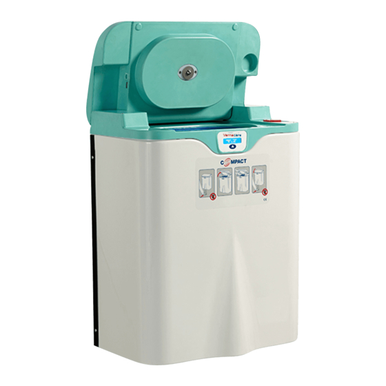
3. General Description 3.1. General description The Vernacare Compact disposal unit is designed to dispose of Vernacare single use products, human waste, toilet tissue and maceratable wipes. No other materials should be placed in the machine. Items to be disposed of are placed in the hopper; the disposal cycle breaks down the contents of the hopper and disperses it in water to form a fine slurry. - Page 8 Drain Valve Vented & Opened Motor Off Deodoriser Pump On (for 2 seconds) Motor On Water Pump On- (for Cleaning) Lid Seal Vented Cycle Completed Page | 8 Vernacare Compact Technical Manual-Revision 3-Issued by N.Shields 11.2018...
- Page 9 Frame Water Tank Power Supply Unit Mitsubishi Inverter Electrical Cabinet 3 Phase AC Motor Lid Assembly Deodoriser Tank Display Overflow & Assembly Hopper Front Panel Foot Sensor Base Panel Page | 9 Vernacare Compact Technical Manual-Revision 3-Issued by N.Shields 11.2018...
- Page 10 3.5. Dimensions of the Vernacare Compact Note that 250mm is the maximum distance allowed between the floor and the foot sensor. The operational range for this dimension is between 220 & 250mm Page | 10 Vernacare Compact Technical Manual-Revision 3-Issued by N.Shields 11.2018...
-
Page 11: Installation / Commissioning
LID CLEARENCE & MACHINE HEIGHT 350mm · A minimum of 350mm clearance is required above the Compact lid. Items fitted to the wall directly above the machine may restrict the lid from opening and operating effectively. · For the foot sensor to operate the machine MUST measure between 220 &... - Page 12 · · Please note that Vernacare recommends bolting the Note that the Compact exceeds 50Kg in weight and is plinth to the floor, if this and other mounting options too heavy for a single person to lift without an aid.
- Page 13 Use the 2 provided M8 x 25 bolts and washers to · The Compact can now be hung onto the wall bracket, fasten the Compact to the bracket as shown. · the 2 hooks on the bracket locate within the slits on Fasten the base plate to the machine (shown bottom the unit back panel as shown.
- Page 14 6 M8 studs. · Please view steps 3 & 4 on the previous page for instructions on fitting a Compact to the wall bracket. Page | 14 Vernacare Compact Technical Manual-Revision 3-Issued by N.Shields 11.2018...
- Page 15 For all installations, an I.E.E. approved disconnection device must be fitted to the final installation. This device shall be positioned in close proximity to the Compact and within easy reach of the operator & shall also be clearly marked as being the disconnecting device for the machine.
- Page 16 Remember, ceiling voids can get very warm. · Avoid running the drain line near or across hot water pipes. · Anti-syphon precautions should be in line with general practice. Page | 16 Vernacare Compact Technical Manual-Revision 3-Issued by N.Shields 11.2018...
- Page 17 3. For all installations, an I.E.E. approved disconnection device must be fitted to the final installation. This device shall be positioned in close proximity to the Compact and within easy reach of the operator & shall also be clearly marked as being the disconnecting device for the machine.
- Page 18 The SERVICE count is reset by the engineer when the machine is serviced. The service count will also trigger a “Service” message on the LCD display once 5,000 cycles have been completed since the last service visit. Page | 18 Vernacare Compact Technical Manual-Revision 3-Issued by N.Shields 11.2018...
- Page 19 The effectively. machine will still run. The drain Drain Seal Pressure (diaphragm) valve The lid is unable to Lid Error Error has failed to operate open or close. effectively. Page | 19 Vernacare Compact Technical Manual-Revision 3-Issued by N.Shields 11.2018...
-
Page 20: Subassemblies & Spares
M6 x 12 Button Hd Screw (x2) 9210073 M6 Nordlock Washer (x2) 9210071 Barbed Seal Flush Fitting 9750100 Motor Star Gasket 9752027 Mechanical Seal 9210092 Cutter Adapter Coupling 9210026 Cutter Blade 9210033 Page | 20 Vernacare Compact Technical Manual-Revision 3-Issued by N.Shields 11.2018... - Page 21 5.2. Diaphragm Assembly PART DESCRIPTION KIT NUMBER ITEM NUMBER 9210306 Diaphragm Spring 9210055 Diaphragm 9210091 Page | 21 Vernacare Compact Technical Manual-Revision 3-Issued by N.Shields 11.2018...
- Page 22 M8 Spring Washer 9750033 Idle Shaft Hinge Block 9210023 Limit Switch 9210175 M3 x 25 Cap Head Screw (x2) 9210101 Micro Switch Cam Ring 9210009 Lid Bottom Moulding 9210002 Page | 22 Vernacare Compact Technical Manual-Revision 3-Issued by N.Shields 11.2018...
- Page 23 5.4. Lid Motor Assembly PART DESCRIPTION KIT NUMBER ITEM NUMBER 9210304 EMS Lid Motor 9210134 M6 x 35 Hex Hd Screws (x2) 9210079 M6 Plain Washers (x2) 9750024 Page | 23 Vernacare Compact Technical Manual-Revision 3-Issued by N.Shields 11.2018...
- Page 24 5.5. Interlock Assembly PART DESCRIPTION KIT NUMBER ITEM NUMBER 9210305 Interlock Solenoid Assembly 9210135 M5 Plain Washer (x2) 9750011 M5 x 8 Pan Posi Hd Screw (x2) 9210105 Interlock Pin 9210021 Page | 24 Vernacare Compact Technical Manual-Revision 3-Issued by N.Shields 11.2018...
- Page 25 9210001 M4 x 20 Cap Hd Screw (x8) 9210063 Hose Cover Panel 9210046 (with captive screw) Top Cover 9210000 Display Assembly 9210307 (see 5.7 for full detail) Seal 9210097 Page | 25 Vernacare Compact Technical Manual-Revision 3-Issued by N.Shields 11.2018...
- Page 26 ITEM NUMBER 9210307 M3 Nut (x2) 9750062 Display Strap 9210184 M3 Plain Washer (x2) 9210056 Start Switch Membrane 9210031 Ribbon Cable LCD Display M3 x 16 CSK Screw (x2) 9210058 Page | 26 Vernacare Compact Technical Manual-Revision 3-Issued by N.Shields 11.2018...
- Page 27 3/8“ BSP (M) to 3/8“ Barbed Elbow 9210163 Nylon Manifold 9210028 1/4” BSP (M) to 6mm Connector 9210162 1/4” BSP (M) to 6mm Connector 9210162 1/4” BSP (M) to 6mm Connector 9210162 Page | 27 Vernacare Compact Technical Manual-Revision 3-Issued by N.Shields 11.2018...
- Page 28 In-Line Non Return Valve 9210167 Overflow Funnel 9210007 40mm (1 ½ ”) P Trap 9210144 40mm Swept Tee 9210145 P Trap Plug 9210029 Straight Nozzle 3/8” BSP x 12mm 9210172 Page | 28 Vernacare Compact Technical Manual-Revision 3-Issued by N.Shields 11.2018...
- Page 29 ‘O’ Ring 16.6 ID x 2.4 DIA Nitrile 9752018 Vent Cowl 9200325 M4 x 10 Pan Hd Screw (x2) 9210062 M4 Plain Washer (x2) 9200540 Vent Connector 9200334 Compact Hopper Tube 9210034 Page | 29 Vernacare Compact Technical Manual-Revision 3-Issued by N.Shields 11.2018...
- Page 30 (x2) SMC (F) R1/8 x 6 Male Elbow 9210187 (x2) SMC Check Valve 6mm 9210188 (x2) 6mm PIF Elbow Connector 9210189 (x2) SMC - PSPP Adapter (1/4”to 6mm) 9210190 6mm Nylon Tubing (various lengths) Page | 30 Vernacare Compact Technical Manual-Revision 3-Issued by N.Shields 11.2018...
- Page 31 Threaded Plug (deodoriser cap) 9210052 Mechanical Seal 9210092 Inflatable ‘D’ Seal 9210099 Water Pump 9210132 Floor LED 9210139 Deodoriser Pump 9210133 40mm P Trap 9210144 3/2 Valve 9210181 Compressor Pump 9210131 Page | 31 Vernacare Compact Technical Manual-Revision 3-Issued by N.Shields 11.2018...
- Page 32 Magnetic Sensor (Lid Safety Sensor) 9200834 Pressure Switch (Lid Seal & Drain 9210137 Valve) Capactitive Sensor 9210127 Magnetic Sensor (Lid Open/Close) 9210136 Pressure Transducer (Drain Switch) 9210212 Ultrasonic Foot Sensor 9210130 Page | 32 Vernacare Compact Technical Manual-Revision 3-Issued by N.Shields 11.2018...
-
Page 33: Pcb Layout
Deodoriser Pump Cable Lid Interlock cable Water Pump Cable IFM Cable ‘ENGINEER MODE’ Push Button Cable Start Button & Toggle Switch Cable Floor LED Cable Lid Seal Valve Cable Page | 33 Vernacare Compact Technical Manual-Revision 3-Issued by N.Shields 11.2018... -
Page 34: Electrical Enclosure
7. Electrical Enclosure MAINS SUPPLY 1PH 230/110v 24V DC EMC FILTER POWER SUPPLY Lid Position Safety Switch D700 INVERTER Page | 34 Vernacare Compact Technical Manual-Revision 3-Issued by N.Shields 11.2018... -
Page 35: Sensor Arrangement
LID OPEN MK5122 MK5122 IFM Magnetic Sensor IFM Magnetic Sensor IFM SPLITTER BOX 10 x M8 M8 1m Long Cable on Sensor M8 1m Long Cable on Sensor EBC0136 Page | 35 Vernacare Compact Technical Manual-Revision 3-Issued by N.Shields 11.2018... -
Page 36: Air & Water Distribution
9. Air & Water Distribution Vernacare Compact Technical Manual-Revision 3-Issued by N.Shields 11.2018... -
Page 37: Ac Motor Information
Power Supply 110V AC socket/plug AC socket/plug Motor socket/plug 10.2. Motor terminal Wiring Diagram Motor wired in Delta for 220 volt input from the invertor unit. Ø Ø Ø Page | 37 Vernacare Compact Technical Manual-Revision 3-Issued by N.Shields 11.2018... -
Page 38: Fault Finding
We recommend using Error Message topping up. Vernacare deodoriser for Check sensor operates correctly Displayed The machine best performance (alternating will continue message) to run as normal Page | 38 Vernacare Compact Technical Manual-Revision 3-Issued by N.Shields 11.2018... - Page 39 ‘DRAIN VALVE’ The drain valve Check airline connections for leaks Error Message has not closed Call maintenance properly Displayed Check Solenoid valve for correct operation. Check diaphragm valve integrity Page | 39 Vernacare Compact Technical Manual-Revision 3-Issued by N.Shields 11.2018...
- Page 40 Call maintenance From Machine solenoid valve for leaks Water leaking from pipework, check the integrity of the tubing & hose clips. Water leaking from flange, check the mechanical seal Page | 40 Vernacare Compact Technical Manual-Revision 3-Issued by N.Shields 11.2018...
- Page 41 Open the small covers next to the hinges to check operation of the lock, motor, Drive shaft broken clutch and to inspect the connection or damaged between motor and lid Page | 41 Vernacare Compact Technical Manual-Revision 3-Issued by N.Shields 11.2018...
Need help?
Do you have a question about the Compact and is the answer not in the manual?
Questions and answers