Table of Contents
Advertisement
Advertisement
Table of Contents

Subscribe to Our Youtube Channel
Summary of Contents for Morini Franco Motori S6-C COMPETITION
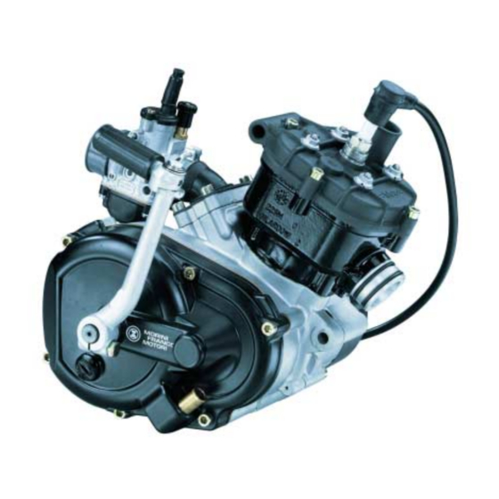
- Page 1 SERVICE MANUAL S6-C COMPETITION 50cc – 2 stroke - liquid cooled...
-
Page 2: Table Of Contents
ENGINE S6 /C INDEX TECHNICAL SPECIFICATIONS SPECIAL TOOLS 3 - 4 PERIODIC MAINTENANCE LUBRICANTS TROUBLESHOOTING 7 - 14 TIGHTENING TORQUE TABLE ENGINE DISASSEMBLY 16 - 24 ENGINE REASSEMBLY 25 - 37 SPECIAL 3-SHOE CLUTCH DISASSEMBLY/REASSEMBLY 38 - 39 SPECIAL 3-SHOE CLUTCH ADJUSTMENT PROCEDURE ENGINE COMPONENT INSPECTION AND SERVICE 41 - 43 GENERAL PARTS LIST + EXPLODED VIEW TABLES... -
Page 3: Specifications
ENGINE S6 /C TECNICAL SPECIFICATIONS SPECIFICATIONS CYCLE ............- 2 stroke Nr. of CYLINDERS ........DISPLACEMENT.......... - 49.908 cc. BORE AND STROKE mm..... - 39 X 41.8 CYLINDER MATERIAL ......... - Aluminium with Ni / Si carbide coating COMPRESSION RATIO ........ - (15.5 ±0.3) : 1 SPARK PLUG .......... -
Page 4: Special Tools
ENGINE S6 /C SPECIAL TOOLS Figure Code Description BEARING INSTALLER 143176 output shaft BEARING INSTALLER 143154 crankshaft BEARING INSTALLER 143156 output shaft 143179 OIL SEAL INSTALLER output shaft OIL SEAL INSTALLER 143180 crankshaft (flywheel + clutch) OIL SEAL MOUNTING PROTECTION 143181 crankshaft (flywheel + clutch) Page 3... - Page 5 ENGINE S6 /C SPECIAL TOOLS Figure Code Description OIL PUMP SHAFT INSTALLER 143155 (pre-assembled) 140558 FLYWHEEL REMOVER 143162 CRANKCASE PULLER SPECIAL CLUTCH ADJUSTMENT TOOL 143294 Page 4...
-
Page 6: Periodic Maintenance
ENGINE S6 /C PERIODIC MAINTENANCE RUNNING-IN RECOMMENDATIONS: During the running-in period, i.e. for approx. the first 500 km on the road, please note as follows: - Do never run the engine at maximum revolutions. - Do never keep the vehicle at maximum speed. - Do not keep the engine at idle speed for longer time. -
Page 7: Lubricants
ENGINE S6 /C LUBRICANTS N.B. Use original MORINI FRANCO MOTORI spare parts only RECOMMENDED LUBRICANTS / ADHESIVES DESCRIPTION CHARACTERISTICS Transmission oil AGIP RADULA 68 SAE 20W Assembly of various parts GR/SM2 GREASE Special assembly GRAPHITISED MOLYCOTE type GREASE Thread-locking glue... -
Page 8: Troubleshooting
ENGINE S6 /C TROUBLESHOOTING The following flow charts give a general outline of the causes and effects when the engine is not running correctly. Descriptions of solutions for a specific cause are general; for more details the reader should consult the disassembly-reassembly manual. LEGEND OF SYMBOLS EFFECT (fault noticed by the user) Possible CAUSE of the fault... - Page 9 ENGINE S6 /C Starting problems Check spark plug and Faulty spark plug or wrong spark plug replace if necessary. heat rating Start the engine with the throttle fully open. Engine flooded Remove the spark plug, The engine rev the engine, install a dry spark plug and restart starts the engine.
- Page 10 ENGINE S6 /C Maximum indicated running speed cannot be reached Disassemble, wash sponge with a Soiled or 50% solution of petrol and 2T oil; clogged leave to dry. Clean the filter box filter using compressed air; re- assemble. Silencer Check the silencer for clogging. obstructed Replace if necessary.
- Page 11 ENGINE S6 /C Poor acceleration / pickup Check the cluth shoe thickness and the clutch springs for stretching. Clutch If excessively worn they should be replaced. Check the exact number of turns Irregular of the air adjusting screw on the acceleration carburetor.
- Page 12 ENGINE S6 /C Incorrect idling speed Adjust the RPM of the idling speed Idling speed (with engine warm) by adjusting the too high or screw on the throttle valve of the too low carburetor. Disassemble the carburetor and clean all parts (nozzles, throttle val- ve, jet needle, float chamber and body) with solvent and dry by using compressed air.
- Page 13 ENGINE S6 /C Noisy engine Incorrect Check the assembly of all gears and transmission parts of the transmission. gears assembly Check the tightening torque of the Loose transmission clutch nut. Transmission noise and rear Check the clutch unit wheel drag at idling speed.
- Page 14 ENGINE S6 /C Noisy engine Check the oil level. Refill if necessary. Noisy gears Check the teeth of the drive gears visually. Replace if signs of damage or wear are evident. Check the clearance between the Noisy piston and the cylinder. If it does cylinder not correspond to the prescribed unit...
- Page 15 ENGINE S6 /C Smokey exhaust Percentage of Replace the fuel in the tank with mixer oil new fuel mixed with 2% of the type of oil indicated in the handbook. Check that the oil is 100% Mixer oil synthetic for separate oil mixer pump use.
-
Page 16: Tightening Torques
ENGINE S6 /C TIGHTENING TORQUES TORQUE DENOMINATION (Nm) Cranckcase bolts 10 - 12 Clutch cover bolts 10 - 12 Flywheel cover bolts 3 - 4 Carburetor manifold bolts 9 -10 Stator clamping bolts 3 - 4 Oil pump clamping bolts 5 - 6 Carburetor clamping screw 3 - 4... -
Page 18: Engine Disassembly
ENGINE S6 / C ENGINE DISASSEMBLY CARBURETOR UNIT TOOL DIAGRAM DESCRIPTION NOTES CODE Disassemble the CARBURETOR BEFORE LOOSEN THE SCREWS CHECK ACTUAL MANIFOLD ANGLE POSITION Loosen the SCREWS and remove the CARBURETOR MANIFOLD THE MANIFOLD IS COMPOSED BY 4 ELEMENTS. Remove the CARBURETOR MANIFOLD BASE including the REED VALVE... - Page 19 ENGINE S6 / C CYLINDER HEAD - CYLINDER - PISTON TOOL DIAGRAM DESCRIPTION NOTES CODE Remove the SPARK PLUG Remove the 4 CYLINDER HEAD BOLTS Remove the 4 CYLINDER HEAD NUTS Remove the CYLINDER HEAD PAY ATTENTION TO THE DOWEL PINS Check the condition of the O-RING HEAD GASKET Replace if excessively worn.
- Page 20 ENGINE S6 / C TOOL DIAGRAM DESCRIPTION NOTES CODE Disassemble the CYLINDER and remove the CYLINDER BASE GASKET Page 18...
- Page 21 ENGINE S6 / C FLYWHEEL SIDE TOOL DIAGRAM DESCRIPTION NOTES CODE MIND THE BRACKET Loosen the clamping BOLTS and INSIDE THE COVER remove the FLYWHEEL COVER Disassemble the FLYWHEEL STATOR ROTOR LOCK NUT CLAMPED WITH Disassemble the FLYWHEEL 143151 LOXEAL ROTOR Remove the PULLEY CLAMPING BOLT...
- Page 22 ENGINE S6 / C TOOL DIAGRAM DESCRIPTION NOTES CODE Remove the PUMP DRIVE BELT Remove the SPECIAL SNAP RING Remove the SPACER RING The following operations can only be carried out after opening the crankcase TOOL DIAGRAM DESCRIPTION NOTES CODE Unscrew the WATER PUMP ROTOR BLOCK THE PUMP SHAFT...
- Page 23 ENGINE S6 / C CLUTCH SIDE TOOL DIAGRAM DESCRIPTION NOTES CODE Disassemble the CLUTCH ONLY IF CLUTCH ADJUSTING PLUG NEEDS TO BE ADJUSTED MAKE SURE TO Remove the OIL DRAIN PLUG DRAIN THE (cross head) ENGINE COMPLETELY Loosen the clamping BOLTS on the cover and remove the CLUTCH COVER Compass tool CLAMPED WITH...
- Page 24 ENGINE S6 / C TOOL DIAGRAM DESCRIPTION NOTES CODE Disassemble the SPECIAL CLUTCH and the 2.5mm SPACER RING Remove the CLUTCH BELL and the 0.8mm SPACER RING Page 22...
- Page 25 ENGINE S6 / C CRANKCASE “OPENING” TOOL DIAGRAM DESCRIPTION NOTES CODE Remove the cylinder STUD BOLTS if BLOCKED WITH necessary LOXEAL Remove the 8 CRANKCASE BOLTS THE CRANKSHAFT IS DRIVEN ONTO THE BEARINGS. Open the CRANKCASE OPEN THE 143162 CRANKCASE FROM FLYWHEEL SIDE USING THE PULLER TOOL...
- Page 26 ENGINE S6 / C TOOL DIAGRAM DESCRIPTION NOTES CODE Remove the OUTPUT SHAFT SNAP RING Remove the OUTPUT SHAFT Inspect the OUTPUT SHAFT BEARING for abnormal play and noise. Replace the bearing if anything unusual occurs. Remove the SNAP RING Remove the BEARING by using a standard bearing remover set.
-
Page 28: Engine Reassembly
ENGINE S6 / C ENGINE REASSEMBLY WATER PUMP PREASSEMBLY TOOL DIAGRAM DESCRIPTION NOTES CODE Preassemble the WATER PUMP SHAFT UNIT by mounting the components in the following order: snap ring + bearing + spacer + bearing and secure with the snap ring. Insert the complete unit in the HALF CRANKCASE FLYWHEEL SIDE Insert the SPACER RING... - Page 29 ENGINE S6 / C CRANKCASE PREASSEMBLY TOOL DIAGRAM DESCRIPTION NOTES CODE LUBRICATE THE Drive the OUTPUT SHAFT BEARING 143176 HOUSING into the half crankcase clutch side and secure with the snap ring LEAVE THE PRINT ON THE BEARING VISIBLE LUBRICATE THE HOUSING Drive the CRANKSHAFT BEARINGS into the half crankcase clutch side and...
- Page 30 ENGINE S6 / C TOOL DIAGRAM DESCRIPTION NOTES CODE Insert the DRIVE SHAFT in the half crankcase clucth side Insert the SNAP RING onto the second output shaft slot (near transmission gear) Insert the OUTPUT SHAFT into the half crankcase clutch side and secure with SNAP RING CRANKCASE “CLOSING”...
- Page 31 ENGINE S6 / C TOOL DIAGRAM DESCRIPTION NOTES CODE Lubricate the CRANKCASE GASKET on both sides. Apply the CRANKCASE GASKET on the half crankcase clutch side using the 2 dowel pins for centering. Assembly the HALF CRANKCASES DO NOT TIGHTEN Fix 1 x BOLT M6X60 in the postion between the stud bolts and the reed valve zone.
- Page 32 ENGINE S6 / C FLYWHEEL SIDE TOOL DIAGRAM DESCRIPTION NOTES CODE Mount the DRIVEN PULLEY on the water pump shaft and position the PUMP DRIVE BELT on the splined section of the crankshaft. Tightening torque 3 - 4 Nm + Secure the pulley with bolt M4x14 Loxeal 83- 54 Mount the SPROCKET and secure...
- Page 33 ENGINE S6 / C TOOL DIAGRAM DESCRIPTION NOTES CODE Install the FLYWHEEL STATOR with the output cable facing the crankcase. Tightening torque Secure the flywheel stator with 3 - 4 Nm 2 BOLTS M4 x 18 Drive in the 2 elastic dowel pins in the cover.
- Page 34 ENGINE S6 / C CYLINDER - PISTON - HEAD UNIT TOOL DIAGRAM DESCRIPTION NOTES CODE WHEN INSTALLING THE PISTON TURN Assemble the ROLLER CAGE, THE ARROW PISTON and PISTON PIN and MARK ON THE secure with CIRCLIPS. HEAD OF THE PISTON TO THE OIL THE PISTON EXHAUST SIDE...
- Page 35 ENGINE S6 / C TOOL DIAGRAM DESCRIPTION NOTES CODE (Cross tighten) Fit the 4 CYLINDER HEAD NUTS on Tightening torque the stud bolts and tighten 12 - 14 Nm. (Cross tighten) Fit the 4 CYLINDER HEAD BOLTS and Tightening torque tighten 10 - 12 Nm.
- Page 36 ENGINE S6 / C CARBURETOR UNIT TOOL DIAGRAM DESCRIPTION NOTES CODE Insert the CARBURETOR MANIFOLD BASE including the REED VALVE. Check the angle position of the MANIFOLD before Assemble the CARBURETOR tightening the MANIFOLD on the base and secure bolts. with 4 BOLTS M6X25.
- Page 37 ENGINE S6 / C CLUTCH COVER TOOL DIAGRAM DESCRIPTION NOTES CODE Drive the WATER CIRCUIT DELIVERY PIPE into place Assemble the SPRING on the sliding gear as shown on the figure. 143167 Lubricate the inside of the spring using GR MU/3 grease. Assemble the SLIDING GEAR on the cover and secure the SPRING between the two stops.
- Page 38 ENGINE S6 / C TOOL DIAGRAM DESCRIPTION NOTES CODE Install and load the RETURN SPRING on the kick starter shaft. Secure the spring on the backstop in the clutch cover. Assemble the SPRING WASHER and secure with the SNAP RING. Place the SPACER on the kick starter shaft and secure with the snap ring.
- Page 39 ENGINE S6 / C CLUTCH SIDE TOOL DIAGRAM DESCRIPTION NOTES CODE Insert the 0.8mm SPACER RING on the crankshaft clutch side. Lubricate the clutch bell operating zone of the crankshaft using the grease type ROCOL ASP MOLYCOTE. Install the CLUTCH BELL Insert the 2.5 mm SPACER RING Install the CLUTCH ON THE CAUTION...
- Page 40 ENGINE S6 / C TOOL DIAGRAM DESCRIPTION NOTES CODE Mount the clutch cover and secure Tightening torque with 6 BOLTS M6 x 30. 10-12 N.m. Insert the OIL DRAIN PLUG + Tightening torque WASHER and tighten. 8-10 N.m. Recommended Pour 250 cc of oil type AGIP Oil type: RADULA 68 SAE 20W and fit the OIL FILLER CAP + GASKET.
- Page 41 ENGINE S6 / C S6 OIL MIXER PUMP TOOL DIAGRAM DESCRIPTION NOTES CODE Preassemble the 2 BEARINGS and SPACER on the OIL MIXER PUMP DRIVE SHAFT and secure with 2 SNAP RINGS. The print on the bearings should face the drive end of the shaft. Lubricate the bearing housing.
- Page 42 ENGINE S6 / C SPECIAL 3-SHOE CLUTCH DISASSEMBLY Remove the 3 special clutch adjusting screws. ATTENTION Each screw contains 1 spring an 2 balls. Remove the 21 Belleville washers. Take note of the assembly configuration. Remove the screw couplings. Unscrew the clutch shoe retainer pawls and remove the flat spring.
- Page 43 ENGINE S6 / C SPECIAL 3-SHOE CLUTCH REASSEMBLY Grassare = Lubricate Apply a thin film of molycote grease on the shoe-holder plate. Insert the clutch shoe socket screws. Lubricate the outer diameter working zone of the 3 bushings with molycote grease. Insert the bushings in the clutch shoe fulcrums.
-
Page 44: Special 3-Shoe Clutch Adjustment Procedure
ENGINE S6 / C SPECIAL 3-SHOE CLUTCH ADJUSTMENT PROCEDURE Screw knob “C” Clutch shoe stop Check pin “A” Clearance “X” = 0.25 mm Place the clutch on the special tool code 143294 and block it using the screw knob “C”. Position the clutch with one of the shoes blocked against the tool clutch shoe stop. -
Page 46: Engine Component Inspection And Service
ENGINE S6/C ENGINE COMPONENT INSPECTION AND SERVICE CYLINDER - PISTON TABLE Value (mm) Part 50cc Cylinder Ø 39 Piston Ø 39 Piston rings : 1)Piston ring 1st slot Ø 39 x 2 - 0.01 - 0.025 2)Piston ring 2nd slot Ø... - Page 47 ENGINE S6/C CYLINDER - PISTON ASSEMBLY SELECTION TABLE CYLINDER - PISTON DIMENSIONS mm ASSEMBLY SIZE CODE CLEARANCE (stamped on part) CYLINDER PISTON + 0,010 - 0,025 ø 39 ø 39 +0,005 - 0,030 + 0,015 - 0,020 ø 39 ø 39 + 0,010 - 0,025 + 0,020...
- Page 48 ENGINE S6/C CYLINDER CHECK -Check the internal surface of the cylinder for signs of seizure or abnormal wear. -Measure the internal diameter of the cylinder using a bore gauge. -Wear limit: Minimum indicated cylinder selection diameter + 0.03mm. -Take measurements in three different positions along the axis of the cylinder.
Need help?
Do you have a question about the S6-C COMPETITION and is the answer not in the manual?
Questions and answers