Table of Contents
Advertisement
Quick Links
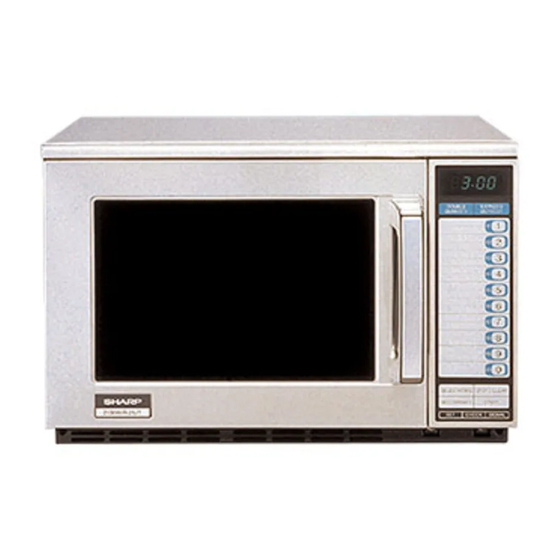
R-24GT
BEFORE SERVICING ........................................................................................................................................... 1
MICROWAVE MEASUREMENT PROCEDURE ................................................................................................... 2
FOREWORD .......................................................................................................................................................... 3
PRODUCT SPECIFICATIONS .............................................................................................................................. 4
GENERAL INFORMATION ................................................................................................................................... 4
OPERATION .......................................................................................................................................................... 6
TROUBLE SHOOTING GUIDE/ TEST PROCEDURE ........................................................................................ 11
TOUCH CONTROL PANEL ................................................................................................................................. 19
COMPONENT REPLACEMENT AND ADJUSTMENT PROCEDURE ................................................................ 28
PICTORIAL DIAGRAM ........................................................................................................................................ 33
CONTROL PANEL CIRCUIT ............................................................................................................................... 35
PRINTED WIRING BOARD ................................................................................................................................. 39
PARTS LIST ........................................................................................................................................................ 40
PACKING AND ACCESSORIES ......................................................................................................................... 46
SHARP ELECTRONICS CORPORATION
Service Headquarters:
SERVICE MANUAL
MODELS
In the interest of user-safety the oven should be restored to its original
condition and only parts identical to those specified should be used.
TABLE OF CONTENTS
Sharp Plaza,
Mahwah,
COMMERCIAL
MICROWAVE OVEN
R-22GV
R-22GT
R-23GT
R-24GT
New Jersey
07430-2135
R-22GV
R-22GT
R-23GT
R-24GT
S7508R24GT///
Page
Advertisement
Table of Contents


Need help?
Do you have a question about the R-22GV and is the answer not in the manual?
Questions and answers