Table of Contents
Advertisement
R-222T(W)
CHAPTER 1. BEFORE SERVICING
CHAPTER 2. WARNING TO SERVICE PERSONNEL
CHAPTER 3. PRODUCT SPECIFICATIONS
CHAPTER 4. APPEARANCE VIEW
CHAPTER 5. OPERATION SEQUENCE
CHAPTER 6. FUNCTION OF IMPORTANT COMPO-
NENTS
CHAPTER 7. TROUBLESHOOTING GUIDE
CHAPTER 8. TEST PROCEDURES
SHARP CORPORATION
SERVICE MANUAL
MODELS
In the interest of user-safety the oven should be restored to its
original condition and only parts identical to those specified
should be used.
CONTENTS
CHAPTER 9. TOUCH CONTROL PANEL ASSEMBLY
CHAPTER 10. COMPONENT REPLACEMENT AND
ADJUSTMENT PROCEDURE
CHAPTER 11. MICROWAVE MEASUREMENT
CHAPTER 12. CIRCUIT DIAGRAMS
Parts List
S7019R222TPJW
MICROWAVE OVEN
R-222T(W)
This document has been published to be used
for after sales service only.
The contents are subject to change without notice.
R-222T(W)
Advertisement
Table of Contents

Related Manuals for Sharp R-222T


Summary of Contents for Sharp R-222T
-
Page 1: Microwave Oven
R-222T(W) SERVICE MANUAL S7019R222TPJW MICROWAVE OVEN R-222T(W) MODELS In the interest of user-safety the oven should be restored to its original condition and only parts identical to those specified R-222T(W) should be used. CONTENTS CHAPTER 1. BEFORE SERVICING CHAPTER 9. TOUCH CONTROL PANEL ASSEMBLY CHAPTER 2. -
Page 2: Table Of Contents
CONTENTS CHAPTER 1. BEFORE SERVICING [13] Procedure M: RELAY TEST......8-5 GENERAL IMPORTANT INFORMATION ..1-1 [14] Procedure N: PROCEDURES TO BE TAK- CAUTION MICROWAVE RADIATION ..1-1 EN WHEN THE FOIL PATTERN ON THE WARNING ..........1-1 PRINTED WIRING BOARD (PWB) IS OPEN............. -
Page 3: Chapter 1. Before Servicing
[1] GENERAL IMPORTANT INFORMATION This Manual has been prepared to provide Sharp Corp. Service engineers with Operation and Service Information. It is recommended that service engineers carefully study the entire text of this manual, so they will be qualified to render satisfactory customer ser- vice. -
Page 4: Chapter 2. Warning To Service Personnel
(timer at zero) carefully check that the water Sharp recommend that wherever possible fault-finding is carried out is now hot. If the water remains cold, carry out 3D checks and re- with the supply disconnected. It may, in some cases, be necessary to examine the connections to the component being tested. -
Page 5: Chapter 3. Product Specifications
R-222T(W) CHAPTER 3. PRODUCT SPECIFICATIONS R200K Service Manual 230 - 240 Volts Power Requirements 50 Hertz Single phase, 3 wire earthed Power Consumption 1.22 kW 800 watts nominal of RF microwave energy (measured by method of IEC) Power Output Operating frequency 2450 MHz... -
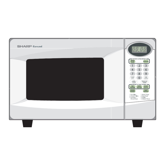
Page 6: Chapter 4. Appearance View
R-222T(W) CHAPTER 4. APPEARANCE VIEW R200K Service Manual [1] OVEN 1. Door open button 2. See-through door 3. Safety door latches 4. Door hinges 5. Door seals sealing surfaces 6. Coupling 7. Roller stay 8. Turntable 9. Ventilation openings 10.Oven lamp 11.Waveguide cover... -
Page 7: Chapter 5. Operation Sequence Off Condition
R-222T(W) CHAPTER 5. OPERATION SEQUENCE R200K Service Manual [1] OFF CONDITION 6. MONITOR SWITCH CIRCUIT The monitor switch is mechanically controlled by oven door, and Closing the door activates all door interlock switches (1st. latch switch, monitors the operation of the 1st. latch switch and the 2nd. interlock 2nd. -
Page 8: Chapter 6. Function Of Important Compo
R-222T(W) CHAPTER 6. FUNCTION OF IMPORTANT COMPONENTS R200K Service Manual [1] DOOR OPEN MECHANISM [6] TEMPERATURE FUSE 150C (OVEN) The door is opened by pulling the door, refer to the Figure D-1. The temperature fuse located on the top of the oven cavity is designed... -
Page 9: Chapter 7. Troubleshooting Guide
R-222T(W) CHAPTER 7. TROUBLESHOOTING GUIDE R200K Service Manual [1] FOREWORD When troubleshooting the microwave oven, it is helpful to follow the IMPORTANT: Sequence of Operation in performing the checks. Many of the possible If the oven becomes inoperative because of a blown fuse T6.3A in the causes of trouble will require that a specific test be performed. -
Page 10: Chapter 8. Test Procedures
R-222T(W) CHAPTER 8. TEST PROCEDURES R200K Service Manual [1] Procedure A : MAGNETRON (MG) TEST NEVER TOUCH ANY PART IN THE CIRCUIT WITH YOUR HAND OR AN INSULATED TOOL WHILE THE OVEN IS IN OPERATION. CARRY OUT 3D CHECKS. Isolate the magnetron from the high voltage circuit by removing all leads connected to the filament terminal. -
Page 11: Procedure B: Power Transformer Test
R-222T(W) 1000g 1000g 1000g T1 C T2 C Heat up for 55 sec. [2] Procedure B: POWER TRANSFORMER TEST WARNING: High voltages and large currents are present at the secondary winding and filament winding of the power transformer. It is very dangerous to work near this part when the oven is on. -
Page 12: Procedure E: Switch Test
R-222T(W) [5] Procedure E: SWITCH TEST CARRY OUT 3D CHECKS. Isolate the switch to be tested and using an ohmmeter check between the terminals as described in the following table. Table: Terminal Connection of Switch Plunger Operation COM to NO COM to NC COM;... -
Page 13: Procedure J: High Voltage Fuse Test
R200K [10] Procedure J: HIGH VOLTAGE FUSE TEST CARRY OUT 3D CHECKS. If the high voltage fuse is blown, there could be a short in the high voltage rectifier or the magnetron. Check them and replace the defective parts and the high voltage fuse. CARRY OUT 4R CHECKS. -
Page 14: Procedure M: Relay Test
R-222T(W) [13] Procedure M: RELAY TEST CARRY OUT 3D CHECKS. Remove the outer case and check voltage between the Pin No. 1 of 3 pin connector (A) and the normal open terminal of the relay RY2 on the control unit with an A.C. voltmeter. The meter should indicate 230 - 240 volts, if not check oven circuit. -
Page 15: Chapter 9. Touch Control Panel Assem
R-222T(W) CHAPTER 9. TOUCH CONTROL PANEL ASSEMBLY R200K Service Manual [1] OUTLINE OF TOUCH CONTROL PANEL This circuit consists of 4-digits, 12-segments and 3-common elec- trodes using a Liquid Crystal Display. The touch control section consists of the following units as shown in 3) Power Source Circuit the touch control panel circuit. - Page 16 R-222T(W) COM2 OUT Common data signal. Connected to LCD signal COM2. COM3 OUT Terminal not used. 26-37 SEG0-SEG11 OUT Segment data signal. Connected to LCD.The relation between signals are as follows: LSI signal (Pin No.) LCD (segment) LSI signal (Pin No.)
-
Page 17: Servicing For Touch Control Panel
R-222T(W) Terminal not used. Terminal not used. BZO90 Signal to sound buzzer (2.0 kHz). A: key touch sound. 0.1 sec. B: Completion sound. H : GND L : -5V 2.0 sec. H : GND L : -5V Terminal not used. -
Page 18: Precautions For Using Lead-Free Solder
R-222T(W) [4] PRECAUTIONS FOR USING LEAD-FREE SOLDER 1. Employing lead-free solder The “Main PWB” of this model employs lead-free solder. This is indicated by the “LF” symbol printed on the PWB and in the service manual. The suffix letter indicates the alloy type of the solder. -
Page 19: Chapter 10. Component Replacement And Adjustment Procedure Before Operating
4) If the outer case (cabinet) is not fitted. 2) Door hinge, support or latch hook is damaged. WARNING FOR WIRING To prevent an electric shock, take the following precautions. 3) Sharp edge: 1. Before wiring, Bottom plate, Oven cavity, Waveguide flange and other metallic plate. -
Page 20: Power Transformer Removal
R-222T(W) [3] POWER TRANSFORMER REMOVAL 1. CARRY OUT 3D CHECKS. 5. Remove the two (2) screws holding the power transformer to bot- tom plate from below. 2. Disconnect the wire leads (main wire harness and H.V. fuse) from power transformer. -
Page 21: Turntable Motor Removal
5. Re-install the turntable motor cover to the bottom plate with one (1) 4. Where the corners have been snipped off bend corner areas flat. screw (XOTS740P08000). No sharp edges must be evident after removal of the turntable motor cover. TTM packing 5. -
Page 22: Power Supply Cord Replacement
R-222T(W) [9] POWER SUPPLY CORD REPLACEMENT 1. REMOVAL 5. Now, the power supply cord is free. 1. CARRY OUT 3D CHECKS. 2. REINSTALL 2. Remove the single (1) screw holding the green/yellow wire to the 1. Insert the moulding cord stopper of power supply cord into the oven cavity back plate. -
Page 23: 1St. Latch Switch, 2Nd. Interlock Relay Control Switch And Monitor Switch Adjustment
R-222T(W) Control panel frame Large Control panel frame depression (Rear side) Liquid crystal Long slit display Small backing paper Slit Contact surface Ribbon cable Ribbon cable of membrane Rubber connector switch Small depression Graphic Membrane sheet switch Figure C-4. Graphic Sheet and Membrane Switch Replacement [12] 1ST. -
Page 24: Door Replacement
R-222T(W) [14] DOOR REPLACEMENT 1. REMOVAL 2) An approved microwave survey meter should be used to assure compliance with proper microwave radiation emission limitation 1. Disconnect the power supply cord. standards. 2. Open the door slightly. 3. After any service, make sure of the following: 3. -
Page 25: Chapter 11. Microwave Measurement
R-222T(W) CHAPTER 11. MICROWAVE MEASUREMENT R200K Service Manual After adjustment of door latch switches, monitor switch and door are completed individually or collectively, the following leakage test must be per- formed with a survey instrument and it must be confirmed that the result meets the requirements of the performance standard for microwave oven. -
Page 26: Chapter 12. Circuit Diagrams
R-222T(W) CHAPTER 12. CIRCUIT DIAGRAMS R200K Service Manual [1] Oven Schematic SCHEMATIC NOTE: CONDITION OF OVEN 1. DOOR CLOSED. 2. CLOCK APPEARS ON DISPLAY. NOTE: " " indicates components with potentials above 250V NOISE FILTER TEMPERATURE FUSE (OVEN) N.O. COM. -
Page 27: Pictorial Diagram (Figure S-1)
R-222T(W) [2] Pictorial Diagram (Figure S-1) Figure S-1. Pictorial Diagram 12 – 2... -
Page 28: Control Unit Circuit (Figure S-2)
R-222T(W) [3] Control Unit Circuit (Figure S-2) Figure S-2. Control Unit Circuit 12 – 3... -
Page 29: Printed Wiring Board (Figure S-3)
R-222T(W) [4] Printed Wiring Board (Figure S-3) Figure S-3. Printed Wiring Board 12 – 4... - Page 30 R-222T(W) MEMO 12 – 5...
-
Page 31: Parts List
R-222T(W) PARTS LIST MICROWAVE OVEN HOW TO ORDER REPLACEMENT PARTS To have your order filled promptly and correctly, please furnish the following information. R-222T(W) MODELS 1. MODEL NUMBER 2. REF. NO. 3. PART NO. 4. DESCRIPTION Parts marked "*" may cause undue microwave exposure. - Page 32 R-222T(W) [1] OVEN PARTS 1-10 4-11 1-13 1-12 4-14 4-16 7-10 4-12 4-17 4-10 4-13 4-13 1-11 1-14 4-15...
- Page 33 R-222T(W) PARTS CODE DESCRIPTION Q'TY PRICE RANK [1] OVEN PART ELECTRIC PARTS QSW-MA085WRE0 1st. latch/ 2nd. interlock relay control switches QSW-MA137WRE0 1st. latch/ 2nd. interlock relay control switches (Interchangable) QSW-MA147WRE0 1st. latch/ 2nd. interlock relay control switches (Interchangable) QSW-MA086WRE0 Monitor switch...
- Page 34 R-222T(W) [2] DOOR AND CONTROL PANEL PARTS 3-1-2 3-1-1...
- Page 35 R-222T(W) PARTS CODE DESCRIPTION Q'TY PRICE RANK [2] DOOR AND CONTROL PANEL PARTS CONTROL PANEL PARTS FPNLCB885WRKZ Control panel frame with key unit 3-1-1 PSHEPB158WREZ Graphic sheet 3-1-2 QSW-KA059DRZZ Membrane switch JBTN-B308WRFZ Open button MSPRCA050WRE0 Open button spring DPWBFC523WRUZ Control unit...
- Page 36 R-222T(W) COPYRIGHT © 2005 BY SHARP CORPORATION ALL RIGHTS RESERVED. No part of this publication may be reproduced, stor- ed in retrieval systems, or transmitted in anyform or by any means, electronic, mechanical, photocopy- ing, recording, or other wise, without prior written...
Need help?
Do you have a question about the R-222T and is the answer not in the manual?
Questions and answers