
Related Manuals for dunkermotoren ServoTube 25


Summary of Contents for dunkermotoren ServoTube 25
- Page 1 ServoTube 25 Type/Typ STA 2504 STB 2504 STA 2506 STB 2506 STA 2508 STB 2508 Instruction Manual STA 2510 STB 2510 ServoTube 25 Publication Ref: UM03011/E Betriebsanleitung ServoTube 25 Publikation Ref: UM03011/E...
-
Page 2: Table Of Contents
1 Content 1 Inhalt 2 About this document 2 Über dieses Dokument 3 General description 3 Allgemeine Beschreibung 3.1 ServoTube 25 Actuator 3.1 ServoTube 25 Aktuator 3.2 ServoTube 25 3.2 ServoTube 25 3.3 Standards and Guidelines 3.3 Normen und Richtlinien... -
Page 3: About This Document
Die vorliegende Betriebsanleitung stellt Ihnen den voTube 25 and provide you with information on all the ServoTube 25 vor und informiert Sie über alle Schritte stages required for the installation of the drive and the zur Installation des Antriebs und zur Durchführung von performance of functional tests. -
Page 4: General Description
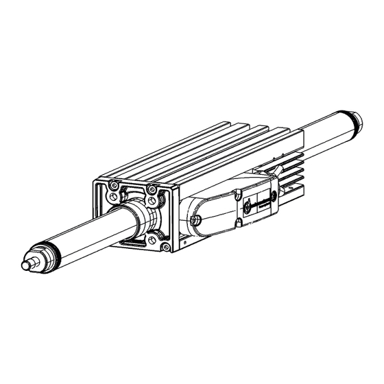
3.1 ServoTube 25 Aktuator (STA) 3.1 ServoTube 25 Actuator (STA) Der ServoTube 25 Aktuator ist eine optimale Lösung The ServoTube 25 Actuator is an optimal solution for für die industrielle Positionieranwendung. Schneller industrial position control. Faster than a ballscrew with... - Page 5 3.2. ServoTube 25 (STB) 3.2 ServoTube 25 (STB) ServoTube 25 delivers the speed of a belt-drive system ServoTube 25 liefert die Geschwindigkeit eines Rie- with the clean reliability of a linear motor at a price menantriebsystems mit der sauberen Zuverlässigkeit unprecedented in the industry.
-
Page 6: Standards And Guidelines
Konformität: Mit der Konformitätserklärung des Conformity: by means of the conformity declaration Produkts bescheinigt Dunkermotoren, dass der Antrieb of the product, Dunkermotoren confirms that the drive den dort aufgeführten Normen zur Sicherheit und EMV complies with the safety standards listed there in and entspricht. -
Page 7: Safety Instructions
Achten Sie auch auf die Lagerbedingungen: Lagerungstemperatur! ► e.g. storage temperature! ► z.B. (See technical data) (Siehe technische Daten) Transport the drive under storage Transportieren Sie die Antriebe unter conditions Lagerbedingungen: protection against shock ► stoßgeschützt ► Version 08.2017 www.dunkermotoren.com... -
Page 8: Warning Symbols And Meanings
General hazard. Follow the advice given. Gefahr! Befolgen Sie die Sicherheitshin- weise. Electrical safety Elektrische Schutzmaßnahmen Das Gerät muss mit Hilfe des grün/gelben elektrischen This equipment must be earthed using the green/ Erdungsleiters geerdet werden. yellow conductor. www.dunkermotoren.de Version 08.2017... - Page 9 It is the responsibility of the User to ensure compliance Der Benutzer ist verantwortlich zur Gewährleistung with any local electrical and EMC regulations in force at der Übereinstimmung mit lokal bindenden Strom-und EMV Bestimmungen, die zum Zeitpunkt der Installati- the time of installation. on geltend sind. Version 08.2017 www.dunkermotoren.com...
-
Page 10: Technical Data
89% at 40°C ambient/ Bei 40°C Dauer-Startkraft auf 89% reduzieren, (3) Based on a 27 mm stroke/ Bedingung: Bewegende Magnetstange mit 27 mm Hub Nutzlast, (4) Based on triangular move over maximum stroke and no payload/ Bedingung: Bewegende Magnetstange mit Dreiecksbewegung über den maximalen Hub, (5) Based on a moving forcer and no playload/ Bedingung: Bewegende Magnetstange und keine Nutzlast www.dunkermotoren.de Version 08.2017... -
Page 11: Sta Force/Velocity Profiles
Velocity (m/s) STA2506S force/velocity STA2506P force/velocity PEAK PEAK CONTINUOUS CONTINUOUS Velocity (m/s) Velocity (m/s) STA2508S force/velocity STA2508P force/velocity PEAK PEAK CONTINUOUS CONTINUOUS Velocity (m/s) Velocity (m/s) STA2510S force/velocity STA2510P force/velocity PEAK PEAK CONTINUOUS CONTINUOUS Velocity (m/s) Velocity (m/s) Version 08.2017 www.dunkermotoren.com... - Page 12 Velocity (m/s) STB2506S force/velocity STB2506P force/velocity PEAK PEAK CONTINUOUS CONTINUOUS Velocity (m/s) Velocity (m/s) STB2508S force/velocity STB2508P force/velocity PEAK PEAK CONTINUOUS CONTINUOUS Velocity (m/s) Velocity (m/s) STB2510S force/velocity STB2510P force/velocity PEAK PEAK CONTINUOUS CONTINUOUS Velocity (m/s) Velocity (m/s) www.dunkermotoren.de Version 08.2017...
-
Page 13: Thermal Specifications
PRIMÄREINHEIT 2504 2506 2508 2510 2504 2506 2508 2510 Einheiten Maximum stroke/Max. Hub 1180 1129 1078 1027 Forcer mass/Gewicht 1.25 1.70 2.25 2.65 1.15 1.60 2.15 2.55 Primäreinheit Thrust rod mass/metre / kg/m Gewicht pro Meter Magnetstange Version 08.2017 www.dunkermotoren.com... -
Page 14: Position Sensor
TTL signals, you can join up in circuit an additional dereingang mit 5V TTL Pegel verarbeiten können, so interface converter (SI10). kann ein zusätzlichen Schnittstellenwandler (SI10) For more information, see Documentation SI10. dazwischengeschalten werden. Nähere Infos siehe Doku SI10. www.dunkermotoren.de Version 08.2017... -
Page 15: Forcer Over Temperature Sensor
Antriebsverstärker oder in der Servosteuerung erkannt the drive amplifier in order to protect the forcer. werden. Um die Primäreinheit schützen zu können, kann die Ausgangsleistung entsprechend reduziert oder komplett ausgeschaltet werden. Version 08.2017 www.dunkermotoren.com... -
Page 16: Cable
Screened / Unscreened/Geschirmt/ Screened/Geschirmt Screened/Geschirmt Ungeschirmt Minimum bending radius-fixed 42 mm 42 mm routing/Kleinster Biegeradius-Feste Leitungsführung Operating temperature-fixed C to/bis +80 C to/bis +80 routing/Betriebstemperatur-Feste Leitungsführung Operating temperature- flexible routing/ C to/bis +80 C to/bis +80 Betriebstemperatur- Flexible Verlegung www.dunkermotoren.de Version 08.2017... -
Page 17: Connections
White/Weiß -COS Brown/Braun +5Vd.c. Yellow/Gelb Green/Grünen +TH (Thermistor) Pink/Rosa -TH (Thermistor) Grey/Grau SIDE VIEW OF POD WITH LID REMOVED Figure C.5- Sensor cable connection at PL1 on the Sensor PCB/ Sensor Kabelverbindung bei PL1 auf der Sensor-Leiterplatte Version 08.2017 www.dunkermotoren.com... -
Page 18: Installation
-25 bis +70 °C Humidity (relative) 0 to 95% non-condensing 0 bis 95% nicht- Luftfeuchtigkeit (relativ) kondensierend Altitude (above mean sea level) 1000 m Betriebshöhe über N.N. 1000 m Overvoltage category Überspannungskategorie Pollution degree Verschmutzungsgrad light industrial leicht industriell www.dunkermotoren.de Version 08.2017... -
Page 19: Mechanical Installation-Sta
User to prevent the thrust rod from gen zu verhindern, vielmehr liegt es in der Verantwor- being ejected from the forcer. tung des Verbrauchers die Magnetstangen daran zu hindern von der Primäreinheit abgestoßen zu werden. Version 08.2017 www.dunkermotoren.com... - Page 20 NOTE 1. ACTUATOR IS DOUBLE ACTING TOLERANCE 72.0 8 MTG HOLES NOTE 2. FLATS AT EACH END ARE NOT M4 x 8 DEEP RECOMMENDED FOR ALIGNMENT PURPOSES 273.0 NOTE 3. TOLERANCE AROUND SWAGED AREA MAY VARY Figure 2.1 Abbildung 2.1 www.dunkermotoren.de Version 08.2017...
-
Page 21: Mechanical Installation-Stb
Kreuzen Sie niemals Kabel innerhalb der Schlepp- kette. • Be careful to prevent the cable from twisting or • Vermeiden Sie während der Installation, dass sich becoming kinked during installation into the drag das Kabel dreht oder in der Schleppkette geknickt chain. wird. Version 08.2017 www.dunkermotoren.com... - Page 22 212.0 M4 x 8 DEEP DETAIL A SCALE 2:1 T - SLOT DETAIL 313.0 THRUST ROD STB2510 29.0 PITCH TYP 62.0 8 MTG HOLES M4 x 8 DEEP 263.0 ALL DIMENSIONS IN MM Figure 2.1 Abbildung 2.1 www.dunkermotoren.de Version 08.2017...
-
Page 23: Electrical Installation
STA UND STB MUSS GEERDET WERDEN. DIES MUST BE EARTHED. THIS CAN BE ACHIEVED KANN DURCH EIN ERDEN DER VERBUNDENEN BY EARTHING THE CONNECTED MECHANICAL MECHANISCHEN TEILE AN DER MASCHINE DES PARTS ON THE USER’S MACHINE. ANWENDERS ERREICHT WERDEN. Version 08.2017 www.dunkermotoren.com... -
Page 24: Maintenance/Service
• Kontrollieren Sie, ob alle Befestigungsteile fest und • Check all fixings are tight and secure. sicher sind. • Check all flexing cables for signs of wear or • Kontrollieren Sie alle fliegenden Kabel, die bewegt damage. werden, auf Abnutzungen oder Schäden. www.dunkermotoren.de Version 08.2017... -
Page 25: Cable Replacement
• Lösen Sie die zwei Schrauben auf der Zugentla- • Loosen the two fixings on the cable clamp. stung. • Pull the cable out through the cable gland. • Ziehen Sie das Kabel durch die Kabelverschrau- bung. Version 08.2017 www.dunkermotoren.com... -
Page 26: Replacement
MICRO CONNECTOR ON PCB, PL1 SENSOR CABLE POWER CABLE CABLE SCREW TERMINAL GLAND CONNECTOR, TB1 Figure 3.1 - Power and Sensor cable connection details in the pod/Abbildung 3.1.- Details zu den Verbindungen von Leistungs- und Logikabeln im Klemmkasten www.dunkermotoren.de Version 08.2017... -
Page 27: Service
7.6 SERVICE 7.6 SERVICE Should you need to return any items to Dunkermotoren Sollten Sie irgendwelche Teile zu Dunkermotoren Linear Systems, before doing so, please call our Sales Linearsysteme zurückgeben müssen, kontaktieren Sie Department. davor bitte unseren Vertrieb. Please note that when returning items it is recommended Bitte beachten Sie bitte, dass bei Rückgaben... -
Page 28: Apprendices
HAFTUNG Dunkermotoren Linear Systems makes no guarantees Dunkermotoren Linear Systems haftet nicht für die of any kind with regard to this manual. Dunkermotoren Angaben in der vorliegenden Bedienungsanleitung. Linear Systems shall not be liable for errors contained Dunkermotoren ist nicht verantwortlich für auftretende herein or for consequential or incidental damages Fehler, sowie Folge-und Nebenschäden, die als Folge... -
Page 29: Troubleshooting Chart
Gegen-EMK versetzt. direction. made incorrectly. ruckartig. Primäreinheit/ Eine oder mehrere Kontrollieren Sie die Magnetstange Motorphaseverbindungen Verbindungen des bewegt sich wurden nicht hergestellt Lagegebers und der in die falsche oder sind inkorrekt. Primäreinheit am Antrieb. Richtung. Version 08.2017 www.dunkermotoren.com... -
Page 30: Terms & Abbreviations
25°C, the forcer is not moving and there is no forced cooling. It is quoted with and without the addition of a 25 x 25 x 2.5cm heatsink plate mounted with thermal grease to the mounting surface of the forcer. www.dunkermotoren.de Version 08.2017... - Page 31 Thermal time constant Thermal time constant is the time taken for the motor phases to cool to 36.8% of the difference between motor phase and ambient temperatures when there is no current flowing, the motor is not moving there is no forced cooling and no additional heatsinking. Version 08.2017 www.dunkermotoren.com...
-
Page 32: Begriffserklärungen & Abkürzungen
Zwangskühlung und der Motor hat keinen zusätzlichen Kühlkörper . Die Werte werden mit und ohne einer zusätzlichen Kühlkörperplatte von 25 x 25 x 2.5 cm gemessen, die mit der Wärmeleitplaste an der Auflagefläche des Motors befestig ist. www.dunkermotoren.de Version 08.2017... - Page 33 EMF/EMK Underwriters Laboratory Elektromotorische Kraft kilogramme/Kilogramm Volt/Volt metre /Meter Volt peak/Spitzenspannung Volt peak-to-peak/Spitze-Spitze milliampere/Milliampere Spannung pk-pk Volt root-mean-square/ millihenry Effektivspannung millimetre/Millimeter Watt/Watt Mounting/Befestigungs- °C degrees Celsius/Grad Celcius Newton/Newton µ micrometre (micron)/Mikrometer Positive Temperature Coefficient/ Positiver Temperatur Koeffizient Version 08.2017 www.dunkermotoren.com...
-
Page 34: Service & Support
Bei Fragen und Problemen stehen Ihnen folgende An- contact: sprechpartner zur Verfügung: - Your local Dunkermotoren sales outlet - Ihre zuständige Vertretung - Your local Dunkermotoren key account manager - Ihr zuständiger Dunkermotoren Key Account - Our hardware support department Manager - Our software support department - Unsere Supportabteilung für Hardware...
Need help?
Do you have a question about the ServoTube 25 and is the answer not in the manual?
Questions and answers