Table of Contents
Advertisement
SERVICE MANUAL
5
4
TH
CLIP
SP
CHANNEL 1
3
PROT
2
1
0
10
5
4
TH
CLIP
SP
CHANNEL 1
3
PROT
2
1
0
10
5
4
CLIP
SP
CHANNEL 1
3
PROT
2
1
0
10
APA1400
APA1000
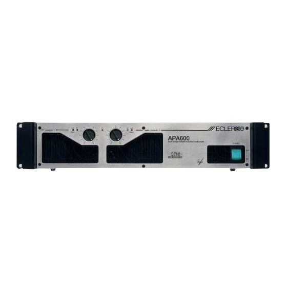
APA600
5
6
4
6
SP
CLIP
TH
7
3
7
PROT
2
8
8
9
1
9
0
10
5
6
4
6
SP
CLIP
TH
7
3
7
PROT
2
8
8
9
1
9
0
10
5
6
4
6
TH
SP
CLIP
7
3
7
PROT
8
2
8
1
9
9
0
10
CHANNEL 2
APA1400
SWITCHING POWER MOSFET AMPLIFIER
CHANNEL 2
APA1000
SWITCHING POWER MOSFET AMPLIFIER
CHANNEL 2
APA600
SWITCHING POWER MOSFET AMPLIFIER
EC
LE
R
POWER
OFF
ON
EC
LE
R
POWER
OFF
ON
EC
LE
R
POWER
OFF
ON
Advertisement
Table of Contents

Related Manuals for Ecler APA1400


Summary of Contents for Ecler APA1400
-
Page 1: Service Manual
APA1400 APA1000 APA600 SERVICE MANUAL CLIP CLIP CHANNEL 1 CHANNEL 2 PROT PROT APA1400 SWITCHING POWER MOSFET AMPLIFIER POWER CLIP CLIP CHANNEL 1 CHANNEL 2 PROT PROT APA1000 SWITCHING POWER MOSFET AMPLIFIER POWER CLIP CLIP CHANNEL 1 CHANNEL 2 PROT... - Page 2 SERVICE MANUAL APA1400/1000/600 INDEX - BLOCK DIAGRAM - FUNCTIONING DESCRIPTION - SCHEMATICS - COMPONENTS LOCATION SCHEMA AND PART LIST - TESTING AND QUALITY CONTROL - TECHNICAL CHARACTERISTICS - WIRING DIAGRAM - CONFIGURATION DIAGRAM - MECHANICAL DIAGRAM - PACKING DIAGRAM...
-
Page 4: Power Module
Queralt 000519 FUNCTIONING DESCRIPTION ECLER author: date: approved: title: POWER MODULE 52.0007 01.00 num: version: The amplifying stage basic structure is actually the one commonly used until now, this is, a push-pull mounted A-B class amplifier, using P-type (IRFP9240) and N-type (IRFP240) mosfets. -
Page 5: Functioning Description
Queralt 000519 FUNCTIONING DESCRIPTION ECLER author: date: approved: title: POWER MODULE 52.0007 01.00 num: version: Moreover, as the helper-transistor's base-emitter current is temperature-dependent, the controlling circuitry (basically the control-transistor) compensates the safe operation area (SOA) drift due to temperature. If the MOSFET's drain-source voltage (Vds) drops too low, a second circuitry actuates... -
Page 17: Parts List
Queralt 020430 PARTS LIST ECLER author: date: approved: model: EP03-99C&D 40.0048 01.01 num: version: PRINTED CIRCUIT 11.0774-01.04 REFERENCE VALUE CODE C101 100n FCXCN41000 C102 100n FCXCN41000 C103 100n FCXCN41000 C104 100n FCXCN41000 C105 47u/16 FCCE100000 C106 47u/16 FCCE100000 C107 47u/16... - Page 18 PRINTED CIRCUIT 11.0774-01.04 REFERENCE VALUE CODE IC101 TL072 FCIC072010 IC102 TL072 FCIC072010 IC103 7815 FCREG78150 IC104 7915 FCREG79150 IC105 TL072 FCIC072010 J101 YKF52-5005 FCBASX0900 J102 YKF52-5005 FCBASX0900 J103 YKB21-5009 FCBASJ0200 J104 YKB21-5009 FCBASJ0200 J105 BASE 4pins MALE FCCTAMP040 J106 BASE 4pins MALE FCCTAMP040 J107 BASE 9pins MALE...
- Page 19 PRINTED CIRCUIT 11.0774-01.04 REFERENCE VALUE CODE R132 715k FCXR157150 R133 178k FCXR151780 R134 36k5 FCXR143650 R135 715k FCXR157150 R136 178k FCXR151780 R137 1k50 FCXR131500 S101 NS42J11 FCINTAP080 S102 17128 FCINTD4000 SC100 M4x12 TR FCT3804012 TS101 T-120 FCTERMF280 W100 19mm FCMECPON19 WI101 1016.04.00 FC2F016400...
- Page 24 Queralt 000913 PARTS LIST ECLER author: date: approved: model: EP03-99C&D 40.0048 01.00 num: version: PRINTED CIRCUIT 11.0774-01.03 REFERENCE VALUE CODE C101 100n FCXCN41000 C102 100n FCXCN41000 C103 100n FCXCN41000 C104 100n FCXCN41000 C105 47u/16 FCCE100000 C106 47u/16 FCCE100000 C107 47u/16...
- Page 25 PRINTED CIRCUIT 11.0774-01.03 REFERENCE VALUE CODE IC101 TL072 FCIC072010 IC102 TL072 FCIC072010 IC103 7815 FCREG78150 IC104 7915 FCREG79150 IC105 TL072 FCIC072010 J101 YKF52-5005 FCBASX0900 J102 YKF52-5005 FCBASX0900 J103 YKB21-5009 FCBASJ0200 J104 YKB21-5009 FCBASJ0200 J105 BASE 4pins MALE FCCTAMP040 J106 BASE 4pins MALE FCCTAMP040 J107 BASE 9pins MALE...
- Page 26 PRINTED CIRCUIT 11.0774-01.03 REFERENCE VALUE CODE R132 715k FCXR157150 R133 178k FCXR151780 R134 36k5 FCXR143650 R135 715k FCXR157150 R136 178k FCXR151780 R137 1k50 FCXR131500 S101 NS42J11 FCINTAP080 S102 17128 FCINTD4000 SC100 M4x12 TR FCT3804012 TS101 IB.311 FCTERMSOL0 W100 19mm FCMECPON19 WI101 1016.04.00 FC2F016400...
- Page 27 01.00 num: version: Announcement addressed to Technical Support Services Involved series: APA1400 / APA1000 / APA600 PAM1100 / PAM2100 MPA4-80 / MPA6-80 / MPA4-150 VOLUME potentiometer replacement. Replaced service part code: FCPR210040 When this potentiometer is being replaced, after soldering it on the printed circuit board, the two leads should be shorted as shown in the picture, in order to ensure a correct performance depending on the available service part.
- Page 30 Queralt 000913 PARTS LIST ECLER author: date: approved: model: EP03-99C&D 40.0049 01.00 num: version: PRINTED CIRCUIT 11.0775-01.01 REFERENCE VALUE CODE D101 LED3G FCLED300VE D102 LED3G FCLED300VE D103 LED3R FCLED300RO D104 LED3Y FCLED300AM D105 LED3R FCLED300RO D106 LED3Y FCLED300AM D107 UNFITTED...
- Page 35 Queralt 000913 PARTS LIST ECLER author: date: approved: model: EP03-99D 40.0050 01.00 num: version: PRINTED CIRCUIT 11.0766-01.02 REFERENCE VALUE CODE C101 FCXCN12200 C102 100n FCXCN41000 C103 47u/50 FCCE250470 C104 10u/50 FCCE250100 C105 FCXCN14700 C106 FCXCN14700 C107 47u/100 FCCE350470 C108 47u/100...
- Page 36 PRINTED CIRCUIT 11.0766-01.02 REFERENCE VALUE CODE D111 Z27V/1 FCDD102700 D112 Z27V/1 FCDD102700 D113 FCDIDB3000 D114 Z8.2V FCXZ000082 D115 Z8.2V FCXZ000082 D116 FCDD041200 D117 FCDD041200 D118 FCDD041200 D119 FCDD041200 D120 FCDD041200 D121 FCDD041200 D122 FCDD041200 D123 FCDD041200 D124 FCDD041200 D125 FCDD041200 D126 BAS16 FCXDDBAS16...
- Page 37 PRINTED CIRCUIT 11.0766-01.02 REFERENCE VALUE CODE J101 B4B-EH-A FCCTM00040 J102 JUMPER PIN FCTERM0100 J103 JUMPER PIN FCTERM0100 J104 JUMPER PIN FCTERM0100 J105 JUMPER PIN FCTERM0100 J106 JUMPER PIN FCTERM0100 J107 JUMPER PIN FCTERM0100 J108 B2B-EH-A FCCTM00020 J109 B2B-EH-A FCCTM00020 J110 B3B-EH-A FCCTM00030 K101...
- Page 38 PRINTED CIRCUIT 11.0766-01.02 REFERENCE VALUE CODE R104 22k1 FCXR142210 R105 FCXR131000 R106 100k0 FCXR151000 R107 FCXR131000 R108 47k5 FCXR144750 R109 FCXR132000 R110 5k62 FCXR135620 R111 51k1 FCXR145110 R112 FCXR071000 R113 1k21 FCXR131210 R114 1k21 FCXR131210 R115 487Ω FCXR124870 R116 191Ω FCXR121910 R117 487Ω...
- Page 39 PRINTED CIRCUIT 11.0766-01.02 REFERENCE VALUE CODE R163 NF220Ω/ 1/2 FCRF232200 R164 NF220Ω/ 1/2 FCRF232200 R165 W0.22Ω/5 FCRY000100 R166 W0.22Ω/5 FCRY000100 R167 NF220Ω/ 1/2 FCRF232200 R168 NF220Ω/ 1/2 FCRF232200 R169 W0.22Ω/5 FCRY000100 R170 W0.22Ω/5 FCRY000100 R171 NF220Ω/ 1/2 FCRF232200 R172 NF220Ω/ 1/2 FCRF232200 R173 W0.22Ω/5...
- Page 40 PRINTED CIRCUIT 11.0766-01.02 REFERENCE VALUE CODE SC106 SCREW M3x10 FCT8030100 SC107 SCREW M3x10 FCT8030100 SC108 SCREW M3x10 FCT8030100 SC109 SCREW M3x10 FCT8030100 SC110 SCREW M3x10 FCT8030100 SC111 SCREW M3x10 FCT8030100 SC112 SPACER FCSEPPM000 SC113 SPACER FCSEPPM000 SC114 SPACER FCSEPPM000 SC115 SPACER FCSEPPM000 SC116...
- Page 41 - Verify both XLR and JACK input terminals, also check the attenuation values by sweeping their potentiometers between -v and 0dB. ∙ Verify the amplifier's output power while connected to the mains power supply: - APA1400 635W 51V on 4Ω...
-
Page 42: First Stage
- Turn on the signal generator, and slowly increase the amplifier's input signal amplitude, while watching that the unit's output voltage does not exceed its limiting value, depending on the type under test, as listed below: FIRST STAGE SECOND STAGE - APA1400 13Vpp 22Vpp - APA1000 20Vpp... -
Page 43: Quality Control
Queralt 011212 VERIFICATION PROCESS ECLER author: date: approved: title: APA POWER AMPLIFIERS 51.0027 01.02 num: version: QUALITY CONTROL All mechanical parts should be visually revised, in order to detect scratches on the unit's painting; all screws should be on their place, correctly tight and unmarked. Check out the unit's general presentation. - Page 44 - Verify both XLR and JACK input terminals, also check the attenuation values by sweeping their potentiometers between -v and 0dB. ∙ Verify the amplifier's output power while connected to the mains power supply: - APA1400 635W 51V on 4Ω...
- Page 45 - Turn on the signal generator, and slowly increase the amplifier's input signal amplitude, while watching that the unit's output voltage does not exceed its limiting value, depending on the type under test, as listed below: FIRST STAGE SECOND STAGE - APA1400 13Vpp (240V) 22Vpp (215V) - APA1000 20Vpp (235V)
- Page 46 Queralt 000519 VERIFICATION PROCESS ECLER author: date: approved: title: APA POWER AMPLIFIERS 51.0027 01.01 num: version: QUALITY CONTROL All mechanical parts should be visually revised, in order to detect scratches on the unit's painting; all screws should be on their place, correctly tight and unmarked. Check out the unit's general presentation.
-
Page 47: Technical Characteristics
J.Colomines 010627 TECHNICAL CHARACTERISTICS ECLER author: date: approved: title: EP03-99D 53.0009 01.02 num: version: POWER 20-20kHz 1% THD 4W Stereo 635 WRMS 8W Stereo 395 WRMS 8W Bridged 1270 WRMS POWER 1kHz 0.1% THD 4W Stereo 590 WRMS 8W Stereo... - Page 52 Nº ECLER Code Description FCMECPM120 BASE CHASSIS FCMECPM130 TOP COVER FCMECPM140 FRONT PANEL WITH TERMINALS DOWN FCMECPM180 FRONTAL HANDLE FCMECPM170 LEFT/RIGHT SIDE FCMECPM100 MECHANICAL REINFORCEMENT DETAIL A FCMECPM110 LED CIRCUIT MEC. SUPORT FCMECPM190 MODULE SUPPORT PLATE 260MM FCVEN08000 FAN 80x80 12VDC...
- Page 53 Nº ECLER Code Description FCMECPM120 BASE CHASSIS FCMECPM130 TOP COVER FCMECPM140 FRONT PANEL WITH TERMINALS DOWN FCMECPM180 FRONTAL HANDLE FCMECPM170 LEFT/RIGHT SIDE FCMECPM100 MECHANICAL REINFORCEMENT DETAIL A FCMECPM110 LED CIRCUIT MEC. SUPORT FCMECPM190 MODULE SUPPORT PLATE 260MM FCVEN08000 FAN 80x80 12VDC...
- Page 54 Nº ECLER Code Description FCMECPM120 BASE CHASSIS FCMECPM130 TOP COVER FCMECPM140 FRONT PANEL FCMECPM180 FRONTAL HANDLE FCMECPM170 LEFT/RIGHT SIDE FCMECPM100 MECHANICAL REINFORCEMENT FCMECPM110 LED CIRCUIT MEC. SUPORT FCMECPM190 MODULE SUPPORT PLATE 260MM FCVEN08000 FAN 80x80 12VDC FCMECPM150 FILTERS PLATE FCTALL4081...
- Page 55 PRODUCT LABEL PACK (ONE FOR EACH UNIT) 1 FCFUNMAN0000 USER MANUAL BAG 1 FCFUS6040000 FUSE 16A 1 FCMANPAMLO00 USER MANUAL APA 4 FCPIE1125500 RUBBER FOOT 1 FCTARJG00000 WARRANTY CARD Jordi Folch 040210 ECLER autor: data: aprovat: títol: PACKING DIAGRAM EP03-99D 32.0046 01.03 número: versió:...
- Page 56 Nº ECLER Code Description FCCAJSTA01 BOX STANDARD 1 FCCANT1180 INTERIOR REINFORCEMENT FCBOLS0200 STANDARD BAG 75x65 FCBOL00100 BAG 60x80 FCPIE11255 RUBBER FOOT FCARN50000 WASHER 5X11,5X0,8M FCARAT3000 SCREW INSULATOR FCBOL00200 BAG 120x180 FCCONX0175 MAINS CABLE 3x1 FCFUNMAN00 USER MANUAL BAG FCMANPAMLO USER MANUAL APA...
- Page 57 Nº ECLER Code Description FCCAJSTA01 BOX STANDARD 1 FCCANT1010 INTERIOR REINFORCEMENT FCBOLS0200 STANDARD BAG 75x65 FCBOL00100 BAG 60x80 FCPIE11255 RUBBER FOOT FCARN50000 WASHER 5X11,5X0,8M FCARAT3000 SCREW INSULATOR FCBOL00200 BAG 120x180 FCCONX0175 MAINS CABLE 3x1 FCFUNMAN00 USER MANUAL BAG FCMANPAMLO USER MANUAL APA...
- Page 62 Queralt 000913 PARTS LIST ECLER author: date: approved: model: EP03-99C 40.0051 01.00 num: version: PRINTED CIRCUIT 11.0766-01.02 REFERENCE VALUE CODE C101 FCXCN12200 C102 100n FCXCN41000 C103 47u/50 FCCE250470 C104 10u/50 FCCE250100 C105 FCXCN16800 C106 FCXCN16800 C107 47u/100 FCCE350470 C108 47u/100...
- Page 63 PRINTED CIRCUIT 11.0766-01.02 REFERENCE VALUE CODE D111 Z27V/1 FCDD102700 D112 Z27V/1 FCDD102700 D113 FCDIDB3000 D114 Z8.2V FCXZ000082 D115 Z8.2V FCXZ000082 D116 FCDD041200 D117 FCDD041200 D118 FCDD041200 D119 FCDD041200 D120 FCDD041200 D121 FCDD041200 D122 FCDD041200 D123 FCDD041200 D124 UNFITTED D125 UNFITTED D126 BAS16 FCXDDBAS16...
- Page 64 PRINTED CIRCUIT 11.0766-01.02 REFERENCE VALUE CODE J101 B4B-EH-A FCCTM00040 J102 JUMPER PIN FCTERM0100 J103 JUMPER PIN FCTERM0100 J104 JUMPER PIN FCTERM0100 J105 JUMPER PIN FCTERM0100 J106 JUMPER PIN FCTERM0100 J107 JUMPER PIN FCTERM0100 J108 B2B-EH-A FCCTM00020 J109 B2B-EH-A FCCTM00020 J110 B3B-EH-A FCCTM00030 K101...
- Page 65 PRINTED CIRCUIT 11.0766-01.02 REFERENCE VALUE CODE R104 22k1 FCXR142210 R105 FCXR131000 R106 100k0 FCXR151000 R107 FCXR131000 R108 47k5 FCXR144750 R109 FCXR132000 R110 5k62 FCXR135620 R111 41k2 FCXR144120 R112 FCXR071000 R113 1k21 FCXR131210 R114 1k21 FCXR131210 R115 487Ω FCXR124870 R116 191Ω FCXR121910 R117 487Ω...
- Page 66 PRINTED CIRCUIT 11.0766-01.02 REFERENCE VALUE CODE R163 NF220Ω/ 1/2 FCRF232200 R164 NF220Ω/ 1/2 FCRF232200 R165 W0.22Ω/5 FCRY000100 R166 W0.22Ω/5 FCRY000100 R167 NF220Ω/ 1/2 FCRF232200 R168 NF220Ω/ 1/2 FCRF232200 R169 W0.22Ω/5 FCRY000100 R170 W0.22Ω/5 FCRY000100 R171 NF220Ω/ 1/2 FCRF232200 R172 NF220Ω/ 1/2 FCRF232200 R173 W0.22Ω/5...
- Page 67 PRINTED CIRCUIT 11.0766-01.02 REFERENCE VALUE CODE SC106 SCREW M3x10 FCT8030100 SC107 SCREW M3x10 FCT8030100 SC108 SCREW M3x10 FCT8030100 SC109 SCREW M3x10 FCT8030100 SC110 SCREW M3x10 FCT8030100 SC111 SCREW M3x10 FCT8030100 SC112 SPACER FCSEPPM000 SC113 SPACER FCSEPPM000 SC114 SPACER FCSEPPM000 SC115 SPACER FCSEPPM000 SC116...
-
Page 68: Technical Characteristics
J.Colomines 010627 TECHNICAL CHARACTERISTICS ECLER author: date: approved: title: EP03-99C 53.0008 01.02 num: version: POWER 20-20kHz 1% THD 4W Stereo 440 WRMS 8W Stereo 275 WRMS 8W Bridged 882 WRMS POWER 1kHz 0.1% THD 4W Stereo 400 WRMS 8W Stereo... - Page 69 Nº ECLER Code Description FCMECPM120 BASE CHASSIS FCMECPM130 TOP COVER FCMECPM140 FRONT PANEL FCMECPM180 FRONTAL HANDLE WITH TERMINALS DOWN FCMECPM170 LEFT/RIGHT SIDE FCMECPM100 MECHANICAL REINFORCEMENT FCMECPM110 LED CIRCUIT MEC. SUPORT DETAIL A FCMECPM190 MODULE SUPPORT PLATE 260MM FCVEN08000 FAN 80x80 12VDC...
- Page 70 Nº ECLER Code Description FCMECPM120 BASE CHASSIS FCMECPM130 TOP COVER FCMECPM140 FRONT PANEL FCMECPM180 FRONTAL HANDLE WITH TERMINALS DOWN FCMECPM170 LEFT/RIGHT SIDE FCMECPM100 MECHANICAL REINFORCEMENT FCMECPM110 LED CIRCUIT MEC. SUPORT DETAIL A FCMECPM190 MODULE SUPPORT PLATE 260MM FCVEN08000 FAN 80x80 12VDC...
- Page 71 Nº ECLER Code Description FCMECPM120 BASE CHASSIS FCMECPM130 TOP COVER FCMECPM140 FRONT PANEL FCMECPM180 FRONTAL HANDLE FCMECPM170 LEFT/RIGHT SIDE FCMECPM100 MECHANICAL REINFORCEMENT FCMECPM110 LED CIRCUIT MEC. SUPORT FCMECPM190 MODULE SUPPORT PLATE 260MM FCVEN08000 FAN 80x80 12VDC FCMECPM150 FILTERS PLATE FCTALL4081...
- Page 72 FUSE 10A 1 FCMANPAMLO00 USER MANUAL APA 4 FCPIE1125500 RUBBER FOOT 1 FCTARJG00000 WARRANTY CARD * FOR 100VAC UNITS, USE FUSE TYPE: FCFUS6030000 FUSE 12.5A 6X32 Jordi Folch 040210 ECLER autor: data: aprovat: títol: PACKING DIAGRAM EP03-99C 32.0045 01.04 número: versió:...
- Page 73 Nº Qty ECLER Code Description 4 FCARAT3000 SCREW INSULATOR 4 FCARN50000 WASHER 5X11,5X0,8 2 FCBOL00100 BAG 60x80 1 FCBOL00200 PLASTIC BAG 120x180 1 FCBOLS0200 STANDARD BAG 75x65 2 FCBOTD2401 ROT. KNOB PROTECTION COVER 1 FCCAJSTA01 BOX STANDARD 1 4 FCCANT1180...
- Page 74 Nº ECLER Code Description FCCAJSTA01 BOX STANDARD 1 FCCANT1180 INTERIOR REINFORCEMENT FCBOLS0200 STANDARD BAG 75x65 FCBOL00100 BAG 60x80 FCPIE11255 RUBBER FOOT FCARN50000 WASHER 5X11,5X0,8M FCARAT3000 SCREW INSULATOR FCBOL00200 BAG 120x180 FCCONX0175 MAINS CABLE 3x1 FCFUNMAN00 USER MANUAL BAG FCMANPAMLO USER MANUAL APA...
- Page 75 Nº ECLER Code Description FCCAJSTA01 BOX STANDARD 1 FCCANT1010 INTERIOR REINFORCEMENT FCBOLS0200 STANDARD BAG 75x65 FCBOL00100 BAG 60x80 FCPIE11255 RUBBER FOOT FCARN50000 WASHER 5X11,5X0,8M FCARAT3000 SCREW INSULATOR FCBOL00200 BAG 120x180 FCCONX0175 MAINS CABLE 3x1 FCFUNMAN00 USER MANUAL BAG FCMANPAMLO USER MANUAL APA...
-
Page 80: Parts List
Queralt 000913 PARTS LIST ECLER author: date: approved: model: EP03-99B 40.0054 01.00 num: version: PRINTED CIRCUIT 11.0775-01.01 REFERENCE VALUE CODE D101 LED3G FCLED300VE D102 LED3G FCLED300VE D103 LED3R FCLED300RO D104 UNFITTED D105 LED3R FCLED300RO D106 UNFITTED D107 LED3Y FCLED300AM R101... - Page 85 Queralt 000913 PARTS LIST ECLER author: date: approved: model: EP03-99B 40.0052 01.00 num: version: PRINTED CIRCUIT 11.0776-01.01 REFERENCE VALUE CODE C101 FCXCN12200 C102 100n FCXCN41000 C103 47u/50 FCCE250470 C104 10u/50 FCCE250100 C105 FCXCN16800 C106 FCXCN16800 C107 47u/100 FCCE350470 C108 47u/100...
- Page 86 PRINTED CIRCUIT 11.0776-01.01 REFERENCE VALUE CODE C153 FCXCN40100 C154 220n/100V FCCDK52200 C156 47n/400V FCCDH71047 C157 100n/400V FCCDH71100 C158 47u/16 FCCE100000 C159 100n FCXCN41000 C160 FCXCN16800 C161 10u/50 FCCE250100 C162 100n FCXCN41000 C163 10u/50 FCCE250100 C164 FCXCN11200 C165 100n FCXCN41000 C166 100n FCXCN41000 C167...
- Page 87 PRINTED CIRCUIT 11.0776-01.01 REFERENCE VALUE CODE D139 Z12V FCXZ000120 D140 LED3R FCLED300RO D141 1N4007 FCXDD40070 D142 LED3R FCLED300RO D143 Z3.9V FCXZ000039 D144 Z8.2V FCXZ000082 D145 FCDD041200 D146 Z18V FCXZ000180 D147 Z27V/1 FCDD102700 D148 LED3R FCLED300RO D150 BAS16 FCXDDBAS16 D151 BAS16 FCXDDBAS16 D152 BAS16...
- Page 88 PRINTED CIRCUIT 11.0776-01.01 REFERENCE VALUE CODE IN102 INSULATING TO126 FCMICTO126 IN103 INSULATING TO126 FCMICTO126 IN104 INSULATING TO126 FCMICTO126 IN105 INSULATING TO126 FCMICTO126 IN106 INSULATING TO126 FCMICTO126 IN107 INSULATING TO126 FCMICTO126 J101 B4B-EH-A FCCTM00040 J102 JUMPER FCTERM0100 J103 JUMPER FCTERM0100 J104 JUMPER FCTERM0100 J105...
- Page 89 PRINTED CIRCUIT 11.0776-01.01 REFERENCE VALUE CODE Q114 BC847B FCXTT08470 Q115 BC857B FCXTT08570 Q116 BC847B FCXTT08470 Q117 BTB24600B FCTI246000 Q118 BC857B FCXTT08570 Q119 BC847B FCXTT08470 Q120 IRFP9240 FCTR243000 Q121 IRFP240 FCTR240000 Q122 IRFP9240 FCTR243000 Q123 IRFP240 FCTR240000 Q124 BF871A FCTR871000 Q125 BD437 FCTR437000 Q126...
- Page 90 PRINTED CIRCUIT 11.0776-01.01 REFERENCE VALUE CODE R120 1k50 FCXR131500 R121 1k50 FCXR131500 R122 56.2Ω FCXR115620 R123 681Ω FCXR126810 R124 1k50 FCXR131500 R125 FCRJG44700 R126 681Ω FCXR126810 R127 10Ω FCXR111000 R128 56.2Ω FCXR115620 R129 56.2Ω FCXR115620 R130 10Ω FCXR111000 R131 NF68Ω/1 FCRF426800 R132 NF68Ω/1...
- Page 91 PRINTED CIRCUIT 11.0776-01.01 REFERENCE VALUE CODE R179 FCRJG44700 R180 1k50 FCXR131500 R181 FCXR071000 R182 56.2Ω FCXR115620 R183 8k25 FCXR138250 R184 100k0 FCXR151000 R185 100k0 FCXR151000 R186 100k0 FCXR151000 R187 681Ω FCXR126810 R188 681Ω FCXR126810 R189 10k0 FCXR141000 R190 1k54 FCXR131540 R191 604Ω...
- Page 92 PRINTED CIRCUIT 11.0776-01.01 REFERENCE VALUE CODE R238 1k50 FCXR131500 R239 5k62 FCXR135620 R240 FCXR132000 R241 487Ω FCXR124870 R242 191Ω FCXR121910 R243 56.2Ω FCXR115620 R244 1k50 FCXR131500 R245 56.2Ω FCXR115620 R246 47k5 FCXR144750 R247 33k2 FCXR143320 R248 33k2 FCXR143320 R249 33k2 FCXR143320 R250 13k0...
- Page 93 PRINTED CIRCUIT 11.0776-01.01 REFERENCE VALUE CODE SC105 SPACER FCSEPPM000 SC106 SPACER FCSEPPM000 SC107 SPACER FCSEPPM000 SC108 SCREW 2.9x9.5 FCT7002909 SC109 SCREW 2.9x9.5 FCT7002909 SC110 SCREW 2.9x9.5 FCT7002909 SC111 SCREW 2.9x9.5 FCT7002909 SC112 SCREW M3x6 FCT7503006 SC113 SCREW M3x6 FCT7503006 SC114 SCREW M3x6 FCT7503006 SC115...
- Page 94 PRINTED CIRCUIT 11.0776-01.01 REFERENCE VALUE CODE W128 19mm FCMECPON19 WA103 TOOTHED WASHER FCARDE0300 WA104 TOOTHED WASHER FCARDE0300 WA105 TOOTHED WASHER FCARDE0300 WA106 WASHER 3.2x6x1 FCARM32010 WA107 WASHER 3.2x6x1 FCARM32010 WA108 WASHER 3.2x6x1 FCARM32010 WA109 WASHER 3.2x6x1 FCARM32010 WA110 WASHER 3.2x6x1 FCARM32010 WA111 WASHER 3.2x6x1...
-
Page 99: Parts List
Queralt 020430 PARTS LIST ECLER author: date: approved: model: EP03-99B 40.0053 01.01 num: version: PRINTED CIRCUIT 11.0774-01.04 REFERENCE VALUE CODE C101 100n FCXCN41000 C102 100n FCXCN41000 C103 100n FCXCN41000 C104 100n FCXCN41000 C105 47u/16 FCCE100000 C106 47u/16 FCCE100000 C107 47u/16... - Page 100 PRINTED CIRCUIT 11.0774-01.04 REFERENCE VALUE CODE IC102 TL072 FCIC072010 IC103 7815 FCREG78150 IC104 7915 FCREG79150 IC105 TL072 FCIC072010 J101 YKF52-5005 FCBASX0900 J102 YKF52-5005 FCBASX0900 J103 YKB21-5009 FCBASJ0200 J104 YKB21-5009 FCBASJ0200 J105 BASE 4pins MALE FCCTAMP040 J106 BASE 4pins MALE FCCTAMP040 J107 BASE 9pins MALE FCCTAMP090...
- Page 101 PRINTED CIRCUIT 11.0774-01.04 REFERENCE VALUE CODE R133 178k FCXR151780 R134 36k5 FCXR143650 R135 715k FCXR157150 R136 178k FCXR151780 R137 1k50 FCXR131500 S101 NS42J11 FCINTAP080 S102 17128 FCINTD4000 SC100 SCREW M4x12 FCT3804012 TS101 T-120 FCTERMF280 W100 19mm FCMECPON19 WI101 1016.04.00 FC2F016400 WI102 1017.04.00 FC2F017400...
- Page 106 Queralt 000913 PARTS LIST ECLER author: date: approved: model: EP03-99B 40.0053 01.00 num: version: PRINTED CIRCUIT 11.0774-01.03 REFERENCE VALUE CODE C101 100n FCXCN41000 C102 100n FCXCN41000 C103 100n FCXCN41000 C104 100n FCXCN41000 C105 47u/16 FCCE100000 C106 47u/16 FCCE100000 C107 47u/16...
- Page 107 PRINTED CIRCUIT 11.0774-01.03 REFERENCE VALUE CODE IC102 TL072 FCIC072010 IC103 7815 FCREG78150 IC104 7915 FCREG79150 IC105 TL072 FCIC072010 J101 YKF52-5005 FCBASX0900 J102 YKF52-5005 FCBASX0900 J103 YKB21-5009 FCBASJ0200 J104 YKB21-5009 FCBASJ0200 J105 BASE 4pins MALE FCCTAMP040 J106 BASE 4pins MALE FCCTAMP040 J107 BASE 9pins MALE FCCTAMP090...
- Page 108 PRINTED CIRCUIT 11.0774-01.03 REFERENCE VALUE CODE R133 178k FCXR151780 R134 36k5 FCXR143650 R135 715k FCXR157150 R136 178k FCXR151780 R137 1k50 FCXR131500 S101 NS42J11 FCINTAP080 S102 17128 FCINTD4000 SC100 SCREW M4x12 FCT3804012 TS101 IB.311 FCTERMSOL0 W100 19mm FCMECPON19 WI101 1016.04.00 FC2F016400 WI102 1017.04.00 FC2F017400...
- Page 109 J.Colomines 010627 TECHNICAL CHARACTERISTICS ECLER author: date: approved: title: EP03-99B 53.0007 01.02 num: version: POWER 20-20kHz 1% THD 4W Stereo 275 WRMS 8W Stereo 180 WRMS 8W Bridged 550 WRMS POWER 1kHz 0.1% THD 4W Stereo 250 WRMS 8W Stereo...
- Page 113 Nº ECLER Code Description FCMECPM120 BASE CHASSIS FCMECPM110 LED CIRCUIT MEC. SUPORT FCMECPM141 FRONT PANEL WITH TERMINALS DOWN FCMECPM180 FRONTAL HANDLE FCMECPM190 MODULE SUPPORT PLATE 260MM FCRAD13810 HEATSINK 260MM DETAIL A FCVEN08000 FAN 80x80 12VDC FCMECPM100 MECHANICAL REINFORCEMENT FCMECPM170 LEFT/RIGHT SIDE...
- Page 114 Nº ECLER Code Description FCMECPM120 BASE CHASSIS FCMECPM110 LED CIRCUIT MEC. SUPORT FCMECPM141 FRONT PANEL WITH TERMINALS DOWN FCMECPM180 FRONTAL HANDLE FCMECPM190 MODULE SUPPORT PLATE 260MM FCRAD13810 HEATSINK 260MM DETAIL A FCVEN08000 FAN 80x80 12VDC FCMECPM100 MECHANICAL REINFORCEMENT FCMECPM170 LEFT/RIGHT SIDE...
- Page 115 Nº ECLER Code Description FCMECPM120 BASE CHASSIS FCMECPM110 LED CIRCUIT MEC. SUPORT FCMECPM141 FRONT PANEL FCMECPM180 FRONTAL HANDLE FCMECPM190 MODULE SUPPORT PLATE 260MM FCRAD13810 HEATSINK 260MM FCVEN08000 FAN 80x80 12VDC FCMECPM100 MECHANICAL REINFORCEMENT FCMECPM170 LEFT/RIGHT SIDE FCREJ08000 FAN GRILLE 80x80...
- Page 116 FUSE 6,3A 1 FCMANPAMLO00 USER MANUAL APA 4 FCPIE1125500 RUBBER FOOT 1 FCTARJG00000 WARRANTY CARD * FOR 100VAC UNITS, USE FUSE TYPE: FCFUS6010000 FUSE 10A 6X32 Jordi Folch 040210 ECLER autor: data: aprovat: títol: PACKING DIAGRAM EP03-99B 32.0044 01.04 número: versió:...
- Page 117 Nº Qty ECLER Code Description 4 FCARAT3000 SCREW INSULATOR 4 FCARN50000 WASHER 5X11,5X0,8 2 FCBOL00100 BAG 60x80 1 FCBOL00200 PLASTIC BAG 120x180 1 FCBOLS0200 STANDARD BAG 75x65 2 FCBOTD2401 ROT. KNOB PROTECTION COVER 1 FCCAJSTA01 BOX STANDARD 1 4 FCCANT1180...
- Page 118 Nº ECLER Code Description FCCAJSTA01 BOX STANDARD 1 FCCANT1180 INTERIOR REINFORCEMENT FCBOLS0200 STANDARD BAG 75x65 FCBOL00100 BAG 60x80 FCPIE11255 RUBBER FOOT FCARN50000 WASHER 5X11,5X0,8M FCARAT3000 SCREW INSULATOR FCBOL00200 BAG 120x180 FCCONX0175 MAINS CABLE 3x1 FCFUNMAN00 USER MANUAL BAG FCMANPAMLO USER MANUAL APA...
- Page 119 Nº ECLER Code Description FCCAJSTA01 BOX STANDARD 1 FCCANT1010 INTERIOR REINFORCEMENT FCBOLS0200 STANDARD BAG 75x65 FCBOL00100 BAG 60x80 FCPIE11255 RUBBER FOOT FCARN50000 WASHER 5X11,5X0,8M FCARAT3000 SCREW INSULATOR FCBOL00200 BAG 120x180 FCCONX0175 MAINS CABLE 3x1 FCFUNMAN00 USER MANUAL BAG FCMANPAMLO USER MANUAL APA...
-
Page 121: Verification Process
Queralt 010425 F01-00 TAWA112/215 ECLER author: date: project: product: approved: title: VERIFICATION PROCESS 51.0044 01.00 num: version: PRELIMINARY: - Connect the verifier’s mains plug, the power ON indicator LED should light up. - Connect TAWA 112 or TAWA 215 to the verifier through the 7-wired bus and both jack- type connectors (right R, left L). - Page 122 - Note : To make the circuit's operation easier to understand, some frequency response curves from the described filters are enclosed. 51-0044-0100 F01-00Anglès.doc Sheet 2 of 3...
- Page 123 51-0044-0100 F01-00Anglès.doc Sheet 3 of 3...
- Page 124 Nº ECLER Code Description FCMECT2649 BASE CHASSIS F01-00 FCT8040060 SCREW M4x6 SPANLO BLACK Jordi Folch 010214 F01-01 TAWA112/215 ECLER drawn: date: project: product: approved: title: MECHANICAL DIAGRAM 30.0151 01.00 number: version...
- Page 125 Nº Qty ECLER Code Description 1 FCBOL0020000 PLASTIC BAG 120x180 1 FCCAJST30000 PACKING CARDBOARD BOX 2 FCCONXJ10000 AERIAL 350mm JACK-JACK CABLE 1 FCETI0951140 PRODUCT LABEL PACK (ONE FOR EACH UNIT) 1 FCMANTAWA000 USER MANUAL 1 FCTARJG00000 WARRANTY CARD Jordi Folch...
- Page 126 Nº Qty ECLER Code Description 1 FCETICAJA1 STICKER 105x37 1 FCCAJST300 PACKING CARDBOARD BOX 2 GENERIC AERIAL 350mm JACK-JACK CABLE 1 FCBOL00200 PLASTIC BAG 120x180 1 FCTARJG000 WARRANTY CARD 1 FCMANTAWA0 USER MANUAL Jordi Folch 010214 F01-01 TAWA112/215 ECLER drawn:...
- Page 130 PARTS LIST: PRINTED CIRCUIT 11.0858.02.00 (TAWA112) Code Description Reference FCXCN40047 C101 FCXCN40047 C102 FCXCN26800 680p C103 FCXCN26800 680p C104 FCCE250470 47u/50 C105 FCCE250470 47u/50 C106 FCXCN21500 150p C107 FCXCN21500 150p C108 FCXCN40047 C109 FCXCN40047 C110 FCXCN42200 220n C111 FCXCN40022 C112 FCXCN42200 220n C113...
- Page 131 PARTS LIST: PRINTED CIRCUIT 11.0858.02.00 (TAWA112) Code Description Reference FCXR151000 100k0 R101 FCXR151000 100k0 R102 FCXR139090 9k09 R103 FCXR139090 9k09 R104 FCXR154750 475k R105 FCXR154750 475k R106 FCXR143320 33k2 R107 FCXR143320 33k2 R108 FCXR142000 20k0 R109 FCXR142000 20k0 R110 FCXR154750 475k R111 FCXR154750...
- Page 132 PARTS LIST: PRINTED CIRCUIT 11.0858.02.00 (TAWA112) Code Description Reference FCXR132000 R163 FCXR141000 10k0 R164 FCXR132430 2k43 R165 FCXR141000 10k0 R166 FCXR131540 1k54 R167 FCXR131540 1k54 R168 FCXR131540 1k54 R169 FCXR131540 1k54 R170 FCXR144750 47k5 R171 FCXR144750 47k5 R172 FCXR144750 47k5 R175 FCXR144750 47k5...
- Page 136 PARTS LIST: PRINTED CIRCUIT 11.0858.02.00 (TAWA215) Code Description Reference FCXCN40100 C101 FCXCN40100 C102 FCXCN26800 680p C103 FCXCN26800 680p C104 FCCE250470 47u/50 C105 FCCE250470 47u/50 C106 FCXCN21500 150p C107 FCXCN21500 150p C108 FCXCN40047 C109 FCXCN40047 C110 FCXCN42200 220n C111 FCXCN40022 C112 FCXCN42200 220n C113...
- Page 137 PARTS LIST: PRINTED CIRCUIT 11.0858.02.00 (TAWA215) Code Description Reference FCXR151000 100k0 R101 FCXR151000 100k0 R102 FCXR139090 9k09 R103 FCXR139090 9k09 R104 FCXR154750 475k R105 FCXR154750 475k R106 FCXR144120 41k2 R107 FCXR144120 41k2 R108 FCXR137870 7k87 R109 FCXR137870 7k87 R110 FCXR154750 475k R111 FCXR154750...
- Page 138 PARTS LIST: PRINTED CIRCUIT 11.0858.02.00 (TAWA215) Code Description Reference FCXR132000 R163 FCXR141000 10k0 R164 FCXR132430 2k43 R165 FCXR141000 10k0 R166 FCXR131540 1k54 R167 FCXR131540 1k54 R168 FCXR131540 1k54 R169 FCXR131540 1k54 R170 FCXR144750 47k5 R171 FCXR144750 47k5 R172 FCXR144750 47k5 R175 FCXR144750 47k5...
Need help?
Do you have a question about the APA1400 and is the answer not in the manual?
Questions and answers