Advertisement
Quick Links
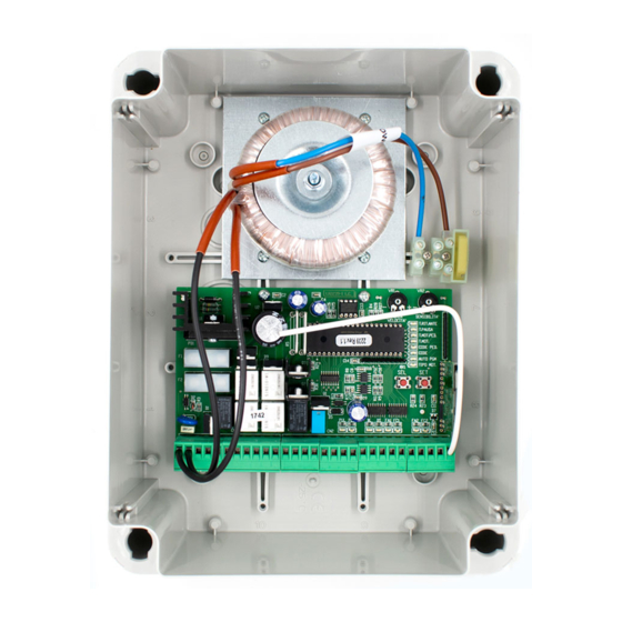
LRX 2239 ELECTRONIC PANEL
12/24*VDC low voltage electronic control unit, for the
automation of swinging and rolling gates with incorporated
receiver and battery charger.
- Mod. LG 2239
- Mod. LRS 2239
- Mod. LRS 2239 SET
- Mod. LRH 2239
TECHNICAL DATA:
- Transformer power supply: 230 Vac 50/60Hz 120W max.
- Control unit power supply: 12 Vac /20*Vac 50/60Hz 120W
max.
- Flashing light output
- Emergency battery input
- Motor outputs
- Electric lock output
- Power supply to photocells
- Indicator light output
- Working temperature
- Radio receiver
- Op. transmitters
- TX max codes in memory
- Dimensions of container
- Protection degree
* If using 24Vdc motors, replace the transformer provided
with a 230/20 Vac transformer the power of which is suited
to the type of motor used (120W max; the outputs for the
flashing light, electric lock and photocell power supply will
adapt to the voltage of 24Vdc, but it is only ever possible
to connect a 12Vdc battery, even when using 24Vdc
motors).
TERMINAL BOARD CONNECTIONS:
CN1 :
1 : Power supply input 12 / 20* Vac 120W max.
2 : Power supply input 12 / 20* Vac 120W max..
3 : Input + Emergency battery 12Vdc 1.2 / 7 Ah max.
4 : Input – Emergency battery 12Vdc 1,2 / 7 Ah max.
5 : Input + Solar panel
6 : Output + Flashing light 12/24*Vdc 4W max.
7 : Output - Flashing light 12/24*Vdc 4W max.
8 : Output + Motor 1.
9 : Output - Motor 1.
10 : Output + Motor 2.
11 : Output - Motor 2.
CN2 :
1 : Electric lock Output (+ 12/24*Vdc 12W).
2 : Electric lock Output (+ 12/24*Vdc 12W).
3 : Control and power supply to photocells (+ 12/24*Vdc 3W ).
4 : Control and power supply to photocells (+ 12/24*Vdc 3W ).
5 : Indicator light output (+ 12Vdc 3W ).
6 : Indicator light output (- 12Vdc 3W ).
7 : Open-Close/Open push button input (NO).
8 : Pedestrian / Close push button input (NO), DS AUX (NC).
9 : Common GND input.
10: Block input (NC).
11: Safety device input (NC).
12: Opening limit switch input for motor 1 (NC).
13: Closing limit switch input for motor 1 (NC).
14: Common GND input.
15: Opening limit switch input for motor 2 (NC).
16: Closing limit switch input for motor 2 (NC).
17: Aerial earth input.
18: Aerial hot pole input.
OPERATING CHARACTERISTICS:
GB
: without radio receiver
: 433.92 Mhz
: 433.92 Mhz "narrow band"
: 868.3 Mhz "narrow band"
: 12/24* Vdc 4 W max.
: 12 Vdc 7A/h max.
: 12/24*Vdc 2 x 50 W max.
: 12/24* Vdc 12W max.
: 12/24* Vdc 3 W max.
: 12 Vdc 3 W max.
: -10 - 55 °C
: refer to type
: 12-18 Bit or Rolling Code
: 120 (CODE or CODE PED)
: 240x190x110 mm.
: IP 56
Automatic:
Using either the radio control (CODE led lit) or the low tension
button panel (PUL) to operate the gates, commands will have
the following effect: the first command impulse activates the
opening mechanism either for the pre-set motor operating
interval or until the activation of the opening limit switch. The
second command impulse closes the gate. If a command
impulse is received before the activation of the limit switch the
direction of movement of the mechanism will be reversed
whether engaged in opening or closing operations.
Step-by-step:
Using either the radio control (CODE led lit) or the low tension
button panel (PUL) to operate the gates, commands will have
the following effect: the first command impulse activates the
opening mechanism either for the pre-set motor operating
interval or until the activation of the opening limit switch. The
second command impulse closes the gate. If a command
impulse is received before the activation of the limit switch the
movement of the mechanism will be stopped. A further
command impulse will reactivate the mechanism in the
opposite direction.
Automatic closing:
The mechanism may be set up to automatically close the gate
without sending additional commands.
The set-up procedure is described in the instructions for setting
the delay period.
Pedestrian access:
Using the radio command (the CODE PED. led is on) or the
button panel (PED), you can activate just motor 1 for the
programmed length of time (T.MOT.PED. led).
Block input:
The control board allows for the connection of a blocking button
(NC). Commands from the button during any phase will
immediately stop the movement of the gate. A further command
will only be executed if the blocking mechanism is deactivated,
and in any case normal automatic opening will work.
If not used the terminals must be jumped.
Safety device:
The control board allows for the connection and control of
photocells in accordance with directive EN 12453.
Commands from the device during the opening phase will be
ignored, and when the gate is closing they will reverse the
direction of movement.
The control board needs the photocells to be connected to their
respective dedicated inputs, otherwise it will not work.
AUX 1 safety device (PED input):
The control unit, when configured, can be fitted with an
Auxiliary 1 safety device together with the Pedestrian Input
(NC).
Commands from the device during the opening phase will stop
the gate temporarily; when reactivated, the control unit
continues the opening phase. Commands whilst the gate is
closing will reverse the direction of movement.
AUX 2 safety device (PED input):
The control unit, when configured, can be fitted with an
Auxiliary 2 safety device together with the Pedestrian Input
(NC).
Commands from the device during an opening or closing phase
temporarily reverse and then stop the movement.
Opening and closing limit switch:
The control unit permits the connection of an Opening and
Closing limit switch for each Motor (NC). Commands from the
limit switches during the respective work phases stop the
respective motors immediately.
Warning: Connect the limit switches, if available;
otherwise do not jump the FA1, FC1, FA2 or FC2 inputs
on the terminal board.
1
Rev. 1.0
08/10/2010
Advertisement

Subscribe to Our Youtube Channel
Related Manuals for Seav LRS 2239


Summary of Contents for Seav LRS 2239
- Page 1 - Mod. LRS 2239 : 433.92 Mhz impulse is received before the activation of the limit switch the - Mod. LRS 2239 SET : 433.92 Mhz “narrow band” direction of movement of the mechanism will be reversed - Mod. LRH 2239 : 868.3 Mhz “narrow band”...
-
Page 2: Main Menu
Initial pick-up and motor power adjustment: SEL key: selects the type of function to be stored; selection is The electronic control unit is equipped with a VR1 trimmer for indicated by a flashing LED. initial pick-up and motor power adjustment that are fully By pressing the key repeatedly, you can select the desired managed by the microprocessor. -
Page 3: Extended Menu
The programming and deleting procedure is the same as the RIT.ANTE LED when flashing then press the SET key twice one illustrated above except that the led selected should be within 2 seconds; the LED goes off and the operation is CODE PED. - Page 4 programming is complete. To enable the Aries (ramming) effect the function proceed as follows: check the extended menu 2 is at the power configured using the VR1 Trimmer, repeat the enabled (the T. PAUSA and RIT. ANTE LEDs flash above procedure, pressing the SEL key twice (the CODE PED simultaneously), press the SEL button until the TIPO MOTOR Led flashes quickly) instead of once.
- Page 5 simultaneously), press the SEL button until the T.MOT.PED Led flashes then press the SET key, at the same time the – OR THE USER IMPORTANT T.MOT.PED turns remains steady - The device should not be used by children or by programming is complete.
- Page 6 3 metres away from each other. SEAV s.r.l. declares that the product: Electronic panel: LG 2239 - LRS 2239 - LRS 2239 SET - LRH 2239 Complies with the requirements of Directives R&TTE 99/5/EC, EMC 2004/108/EC, LVD 2006/95/EC. Rev. 1.0...
- Page 7 Rev. 1.0 08/10/2010...
Need help?
Do you have a question about the LRS 2239 and is the answer not in the manual?
Questions and answers