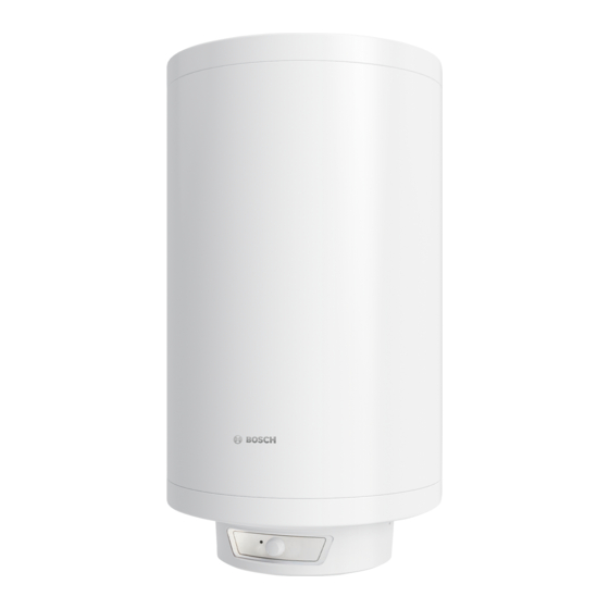
Bosch Tronic 4000 T Series Installation And Operating Instructions Manual

Bosch Tronic 4000 T Series Installation And Operating Instructions Manual

Dhw cylinder
Hide thumbs Also See for Tronic 4000 T Series:

Advertisement

6720818520-00.1V
DHW cylinder
Tronic 4000 T | Tronic 6000 T
ES 035/050/080/100/120/150 5 ...
Installation and operating instructions

Advertisement

Table of Contents
loading

Summary of Contents for Bosch Tronic 4000 T Series

  • Page 1 6720818520-00.1V DHW cylinder Tronic 4000 T | Tronic 6000 T ES 035/050/080/100/120/150 5 ... Installation and operating instructions...
  • Page 2: Table Of Contents

    2 | Table of Contents Table of Contents Regular maintenance ....12 Explanation of symbols and safety instructions . . . 3 8.2.1 Function check ..... . 13 Explanation of symbols .
  • Page 3: Explanation Of Symbols And Safety Instructions

    Explanation of symbols and safety instructions | 3 Installation and conversion Explanation of symbols and safety ▶ Only permit an authorised contractor to install or convert instructions this DHW cylinder. ▶ Never plug the drain of the pressure relief valve. Explanation of symbols ▶...
  • Page 4: Technical Properties And Dimension's

    4 | Technical properties and dimension's appliance. Cleaning and user maintenance [BO] Make [H1, M1] Design shall not be made by children without Standard diameter supervision.” Capillary temperature controller Thermometers “If the power cable is damaged, it must be Wall-mounted installation replaced by the manufacturer, its customer Vertical installation service department or a similarly qualified...
  • Page 5: Technical Data

    Technical properties and dimension's | 5 Technical data This appliance meets the requirements specified by the European Directives 2014/35/EC and 2014/30/EC. Tronic 4000 T Technical data Units ES 050 ES 080 ES 100 ES 120 ES 150 General Information Capacity Dry weight 18,8 22,5...
  • Page 6: Dimensions

    6 | Technical properties and dimension's Dimensions min. 220 max. 300 ØG1/2'' Ø470 6720818520-01.1V Fig. 2 Dimensions in mm (vertical installation) Device ES035... ----- ES050... ES080... ES100... ES120... 1110 1030 ES150... 1329 1144 1250 >500 Table 6 6720818520-02.1V Fig. 3 Dimensions in mm (horizontal installation) 6 720 818 731 (2016/07) Tronic 4000 T | Tronic 6000 T...
  • Page 7: Appliance Layout

    Regulations | 7 Appliance layout Regulations The applicable local standards regarding the installation and handling of electrical DHW cylinders must be observed. Transport ▶ Do not let the DHW cylinder fall. ▶ Transport the storage tank in the original packaging, and use suitable means of transportation.
  • Page 8: Selecting The Installation Location

    8 | Installation Selecting the installation location Wall mounting bracket CAUTION: CAUTION: Danger from falling device! ▶ Select a wall for mounting the cylinder that ▶ Use screws and wall mounting brackets has sufficient load bearing capacity to suitable for the type of wall, with support the full DHW cylinder.
  • Page 9: Water Connection

    Installation | 9 ▶ Use suitable accessories for the hydraulic connection of Device the DHW cylinder. ES050... ES080... ES100... ES120... ES150... Table 7 Water connection NOTICE: Corrosion damage to the DHW cylinder's connections! ▶ Provide the water connections with insulating dielectric unions. This prevents current (DC current) from flowing between the metal hydraulic connections and the resulting corrosion.
  • Page 10: Electrical Connection

    10 | Operating the appliance Commissioning NOTICE: ▶ Check for correct installation of the DHW cylinder. NEVER CLOSE OFF THE PRESSURE RELIEF ▶ Open the water valves. VALVE DRAIN. ▶ Open all of the hot water taps and completely vent the Never install accessories between the pressure water lines.
  • Page 11: Adjust The Domestic Hot Water Temperature

    Operating the appliance | 11 Adjust the domestic hot water temperature Draining the DHW cylinder ▶ Isolate the DHW cylinder from the power supply. The DHW cylinder stops heating once the water reaches the required temperature, and the ON DANGER: Risk of scalding! indicator goes dark (Fig.
  • Page 12: Environmental Protection/Recycling

    Environmental protection/Recycling Maintenance/inspection Environmental protection is a fundamental corporate strategy Only authorised contractors are permitted to of the Bosch Group. maintain this appliance. Product quality, efficiency and environmental protection are equally important objectives for us. We comply with all environmental protection laws and regulations.
  • Page 13: Function Check

    Maintenance/inspection | 13 8.2.1 Function check ▶ Check that all components are functioning correctly. CAUTION: Damage to the enamel coating! Never clean the enamel-coated inner walls of the DHW cylinder using a descaling agent. No additional products are necessary to protect the enamel coating.
  • Page 14: Safety Thermostat

    14 | Maintenance/inspection Safety Thermostat The DHW cylinder is equipped with an automatic safety device. This safety device isolates the DHW cylinder from the power supply to prevent the risk of injury if the DHW cylinder water temperature rises above a certain limit. DANGER: Only authorised contractors are permitted to troubleshoot the temperature limiter.
  • Page 15: Faults

    Faults | 15 Faults Fault/cause/remedy The following table describes troubleshooting procedures for DANGER: possible faults (these must only be carried out by authorised Installation, maintenance and repair work may contractors). only be carried out by an authorised contractor. Problem Reason Remedy Overvoltage or the safety switch was triggered ▶...
  • Page 16 Bosch Thermotechnik GmbH Junkersstrasse 20-24 D-73249 Wernau www.bosch-thermotechnology.com...

Table of Contents