Sign In
Upload
Download
Table of Contents
Contents
Add to my manuals
Delete from my manuals
Share
URL of this page:
HTML Link:
Bookmark this page
Add
Manual will be automatically added to "My Manuals"
Print this page
×
Bookmark added
×
Added to my manuals
Manuals
Brands
Scotsman Manuals
Ice Maker
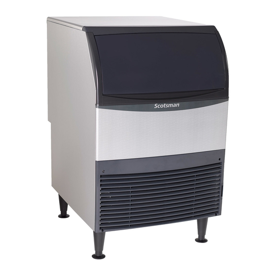
UF424A-1A
Technical manual
Scotsman UF424A-1A Technical Manual
Hide thumbs
1
Table Of Contents
2
3
4
5
6
7
8
9
10
11
12
13
14
15
16
17
18
19
20
21
22
23
24
25
26
27
28
29
30
31
32
33
34
35
page
of
35
Go
/
35
Contents
Table of Contents
Troubleshooting
Bookmarks
Table of Contents
Table of Contents
Specifications
Cabinet Drawing
Plan and Front Views
Side and Back Views
Operational Data
Placement
Installation
Initial Start up
Maintenance and Cleaning
Condensers and Air Filter Cleaning
Operation
Basic Troubleshooting
Controller Functions
Controller Details
Controller Diagnostics
Electrical Sequence
Testing Compressor
Replace Compressor
Replace Fan Motor
Testing Sensors
Panel Removal
Remove Ice Storage bin
Remove Gear Reducer
Remove Auger
Replace Evaporator
Replace Auger Motor
Prep to Replace Water Seal or Bearings
Replace Water Seal and Auger Bearings
Replace Electrical Components
Schematic Diagram
Wiring Diagram
Advertisement
Quick Links
1
Specifications
2
Installation
3
Maintenance and Cleaning
4
Basic Troubleshooting
Download this manual
Technical Manual for
Model UF424 and UN324
Table of
Contents
Previous
Page
Next
Page
1
2
3
4
5
Advertisement
Table of Contents
Need help?
Do you have a question about the UF424A-1A and is the answer not in the manual?
Ask a question
Questions and answers
Related Manuals for Scotsman UF424A-1A
Ice Maker Scotsman UN324A-1A Technical Manual
(35 pages)
Ice Maker Scotsman UN0815A-1A User And Installation Manual
(21 pages)
Ice Maker Scotsman UF0915A-1A User And Installation Manual
(21 pages)
Ice Maker Scotsman UF1415A-1A User And Installation Manual
(21 pages)
Ice Maker Scotsman UN1520A-1A User And Installation Manual
(21 pages)
Ice Maker Scotsman UC2024 Series Service Manual
(40 pages)
Ice Maker Scotsman UC2024 Technical Service Training
(65 pages)
Ice Maker Scotsman UC2024MA-1A Service Manual
(40 pages)
Ice Maker Scotsman UC2024MW- 1A Service Manual
(40 pages)
Ice Maker Scotsman UC2724MA-1A Service Manual
(40 pages)
Ice Maker Scotsman UF424 Installation And User Manual
(2 pages)
Ice Maker Scotsman UF0915 User Manual
(4 pages)
Ice Maker Scotsman UCF 160 Service Manual
(30 pages)
Ice Maker Scotsman CU50PA-1 Installation And User Manual
Cube ice machine (17 pages)
Ice Maker Scotsman CME1356R User Manual
Scotsman ice systems ice maker user manual (47 pages)
Ice Maker Scotsman CU50 Service Manual
Scotsman ice systems ice maker user manual (30 pages)
This manual is also suitable for:
Uf424w-1a
Un324a-1a
Un324w-1a
Un324a-6a
Uf424a-6a
Table of Contents
Save PDF
Print
Rename the bookmark
Delete bookmark?
Delete from my manuals?
Login
Sign In
OR
Sign in with Facebook
Sign in with Google
Upload manual
Upload from disk
Upload from URL


Need help?
Do you have a question about the UF424A-1A and is the answer not in the manual?
Questions and answers