Table of Contents
Advertisement
Advertisement
Table of Contents

Related Manuals for Furuno VR-5000


Summary of Contents for Furuno VR-5000
- Page 1 VOYAGE DATA RECORDER VR-5000 (Serial number 1001 or greater) www.furuno.co.jp...
- Page 2 • Store this manual in a convenient place for future reference. • FURUNO will assume no responsibility for the damage caused by improper use or modification of the equipment (including software) by an unauthorized agent or a third party.
- Page 3 Batteries should be recycled. leaks into the equipment or the equip- Contact FURUNO dealer. ment is emitting smoke or fire. Continued use can cause fatal damage to the equipment.
- Page 4 CAUTION AT POWER-ON In the DCU, confirm that the LEDs SYS1, SYS2, and SYS3 light in orange and DCU OK in green after the power has been on two minutes. If not, see code tables in section 3.2. Procedure for turning on power 1.
-
Page 5: Table Of Contents
CONTENTS INTRODUCTION............................ V SPECIFICATIONS..........................VII SYSTEM CONFIGURATION ........................ IX Chapter 1 OPERATION ........................1.1 1.1 OVERVIEW ..........................1.1 1.2 OPERATING PROCEDURE ....................1.5 1.3 OPERATION ON REMOTE ALARM PANEL ................1.6 1.4 LED STATUS........................... 1.7 1.5 COPY OF VDR INFORMATION ..................... 1.7 1.6 HOW TO REMOVE DRU...................... -
Page 6: Introduction
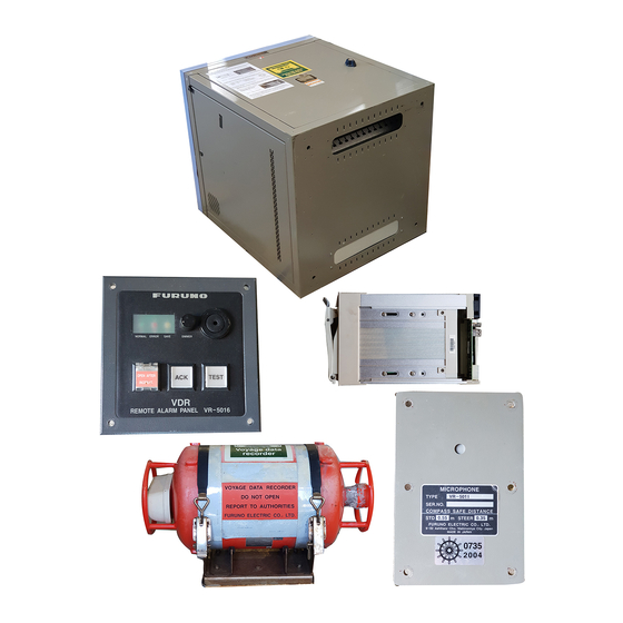
1 July, 2002. Composition The basic VR-5000 consists of a Data Collection Unit (DCU), a Data Recording Unit (DRU) and microphones to record bridge audio. The DCU contains the Data Processor Unit, interface modules and backup batteries. -
Page 7: Specifications
SPECIFICATIONS Standards IMO A.861(20), IEC 61996, A.694, IEC 60945, IEC 61162, etc. Data collecting unit (DCU) Structure of DCU Deck mounted, containing status LEDs, interface, processor unit, power supply for all VDR operation, and backup batteries. Processor CPU: Intel Pentium III in PGA 370 socket Memory: 512 MB (256 MBx2 PC-100/133 SDRAM Interface Serial data interface: 8 (16) channels... - Page 8 Automatically switched on, working for 30 days. Battery life 6 years. Maximum working depth: 6,000 m Data retrieval By playback equipment (not part of standard VR-5000) Power supply Normally taken from DCU. Integral batteries are capable of running the beacon for 30 days and the final recording medium for 2 years.
- Page 9 MANUFACTURER’S DECLARATION Quality assurance Furuno Electric Co., Ltd. Markets a wide range of industrial equipment and systems for aviation electronics, land survey and factory controls, and comprehensive range of marine electronic equipment and systems. Furuno is certified to ISO 9001 by Lloyd’s Register Quality Assurance Limited.
-
Page 10: System Configuration
IEC61162 Anemometer Fire detection (8 ch, 16 ch max) Main alarms Others *: One of IEC 61162 channels used Fig. A System Configuration of VR-5000 Environmental category DCU, RAP Protected from weather Exposed to weather Microphone Protected from weather VHF I/F unit... - Page 11 This page is intentionally left blank.
-
Page 12: Chapter 1 Operation
2 h from backup batteries. Continuity of storing data The VR-5000 should be provided with power to store data for 12 h on first-in, first-out basis. Recording is only terminated with a key under the following circumstances: a) During essential maintenance while the vessel is in port. - Page 13 non-halogen Firewire cable or IEEE1394. Data Collecting Unit The Data Collecting Unit (DCU) mainly consists of Data Processor Unit, Power Distribution Unit and Junction Box. The DCU includes two 12 V backup batteries with a lifetime of approximately four years. The DCU collects the data from various sensors and radar and records them in the flash memory in the capsule (final recording medium).
- Page 14 The microphones are labelled Mic1, Mic2, etc. Microphone captures conversation in the bridge, audio signals from equipment and sound from machinery. The microphone generates a test beep every 12 hours which is also recorded. The microphone picks up audio signals ranging from 150 to 6000 Hz. Communications audio A maximum of two VHF communications are recorded for both transmitted and received audio signals.
- Page 15 Watertight and fire door status The DCU obtains the IMO mandatory watertight and fire door status signals. The inputs, digital or RS-422 serial data are recorded individually with time stamps. Serial data sentence XDR is received at a data rate of 1,200-9,600 baud. Acceleration and hull stresses The DCU obtains signals from appropriate hull stress and response monitoring devices.
-
Page 16: Operating Procedure
1.2 OPERATING PROCEDURE The VDR comes with three keys for the protection against any unauthorized access. The key must be kept securely after installation. Three keys are used; 1) To open the front door of the Data Collecting Unit to gain access to the power switch, 2) To open the door of the removal hard disk (HD). -
Page 17: Operation On Remote Alarm Panel
Note: Every time the radar connected to the VDR is turned off, the alarm sounds. Press ACK button to stop alarm sound. *: If the HD is removed after stopping data recording onto HD, data can not be written to the same HD. To use the same HD, consult a FURUNO serviceman. -1.6-... -
Page 18: Led Status
1.4 LED STATUS The LEDs on the Power Distribution Unit (PDU) operates as follows. Table 1.1 Status of LEDs LEDs Status Remarks Green Presence of AC mains Green Presence of DC supply if connected BATTERY Green Presence of DC from reserve battery (During charging) (Blinking) DCU OK... -
Page 19: How To Remove Dru
The green LED (right) on the panel is “Power” indicator and the amber one (left) is HD access indicator. Key lock Cartridge frame Power indicator Lever HD access indicator Front panel of removable hard disk To remove the HD when an incident occurs, carry out the following procedure. Note: Pressing the SAVE button is permitted only when an incident occurs. -
Page 20: Chapter 2 Maintenance
Chapter 2 MAINTENANCE Periodic checks and maintenance are important for proper operation of any electronic systems. This chapter contains maintenance instructions to be followed to obtain optimum performance and the longest possible life of the equipment. This chapter, except for 2.1 Routine check, is provided for a qualified personnel. WARNING ELECTRICAL SHOCK HAZARD Do not open the equipment. - Page 21 Note that the batteries should be recycled. Contact FURUNO dealer. To replace the batteries; Open the front cover with the key. Remove four upset screws on the power distribution unit and pull out the unit. Power distribution unit Pan head screw...
-
Page 22: Replacing Acoustic Beacon
2.3 REPLACING ACOUSTIC BEACON The underwater acoustic beacon has a built-in battery with approx 6 year lifetime. The beacon must be replaced with new one (type: DK-120, P/No. 000-148-648) by a qualified service engineer before validity date marked on the beacon. 1. -
Page 23: Replacing Hd
The HD records navigation data for more than past 12 hours. For longer recording, use Live Player Backup. 1. Open the DCU with its key. Turn off the VR-5000 by pressing BATTERY, DC, and AC switch in this order. 2. Pull the lever outward and then unlock the key on the HD. (Position C, downward) 3. -
Page 24: Chapter 3 Troubleshooting
Chapter 3 TROUBLESHOOTING This chapter provides information on possible causes of problems you may experience with your VDR. If you still have a problem after referring to the table, contact your local dealer or national distributor for further advice. Always provide the product serial number. 3.1 GENERAL TROUBLE FINDING Use table 3.1 to identify the trouble. -
Page 25: Operating Status
Indicates system is in IDLE-MODE. Indicates system has been in IDLE and is now preparing to get running. Indicates MIC-TEST passed on the selected MICROPHONES. Indicates VR-5000 is rebooting. Indicates only 1 Backup-slot left on multi-incident BACKUPDRIVE. Indicates NO MORE ROOM on BACKUPDRIVE. - Page 26 DCU OK Code Name YELLOW YELLOW YELLOW YELLOW Indicates VR-5000 has been turned on. Wait for 2 minutes to watch LED's Description: start 'roll-flash'. If LED's does not change after 2-3 minutes, system is unable to start normally. Call for maintenance.
- Page 27 PRC_STATUS_CONFIG_INVALID_FLASH_HANDLE This LED-indication is displayed when the CONFIG_area in the DRU is corrupt/wrong/un-initialized. This should only happen during installation/service and if using a DRU not initialized by the VR-5000 it is connected to. Description: Clear CONFIG_area and restart VR-5000. This will install a ’default’...
- Page 28 Name YELLOW YELLOW PRC_RECORDING_STOPPED_INDICATION The VR-5000 has stopped recording. The system has been running on BATTERY only, for more than 2 hours or the index has been cleared and system has not been rebooted. Description: Reconnect AC or DC. And the system will start recording after 30 sec.
- Page 29 SYS 1 SYS 2 SYS 3 DCU OK Code Name GREEN GREEN YELLOW PRC_STATUS_RUNNING_ON_BATTERY Both AC and DC power has been lost. Audible alarms will only be for max 2 min. Description: Reconnect AC or DC power Action: SYS 1 SYS 2 SYS 3 DCU OK...
-
Page 30: Chapter 4 Location Of Parts
Chapter 4 LOCATION OF PARTS Data Processor Unit (DPU)* Removable Hard Disk Cover Power Distribution Unit (PDU) Junction box Cable clamp *: To pull out the PDU, first pull out the DPU. Data Collecting Unit (DCU) -4.1-... - Page 31 Digital IF Board Frame Grabber Board (w/ Multiplexer) Analog IF Board Video Board Audio Analog Board LED Control Board Fire Wire Board Power Supply Unit 256 MB RAM 2 pcs Mother Board or 512 MB RAM 1 pc Removable Hard Disk DPU Processor Board Data Processor Unit (DPU) Note: Lithium battery CR2032 is installed on the DPU Processor Board.
- Page 32 FIREWIRE DIGITAL AUDIO VIDEO Hard disk (top) and (VD1, VD2, VD3 and LED INTF DRU (bottom) VD4 from bottom) 24 VDC ANALOG SERIAL 1 COM 1, COM 2 (top) SERIAL 2 (to add extra serial 8 channels) Main Control Unit, Rear view PDU Board AC/DC power pack BNC connectors...
- Page 33 J46 (RS422) J47 (RS422, optional) MAIN JB Board J35 (Digital) J2 (Analog) J3 (Audio) SUB JB Board Junction Box (JB), Rear view CONNECTOR Board FLASH DISK Board (24P0042) (FW-ATA2501-1) Underwater Acoustic Beacon (DK-120) CONNECTION Board (24P0087) 2.5-inch FLASH DISK (SLFLD25-8GM1U1 (for 6G) or DK0090G88TNO (for 9G)) REPEATER Board (24P0080)
- Page 34 This equipment contains complex modules in which fault diagnosis and repair down to component level are not practical (IMO A.694(17)/8.3.1. Only some discrete components are used. FURUNO Electric Co., Ltd. believes identifying these components is of no value for shipborne maintenance; therefore, they are not listed in this manual. Major modules can be located on the parts location on previous pages.
- Page 35 Module Type Code No. Remarks Breaker III-FII2-PIMI-16A DC and BAT Breaker III-FII2-PIMI-3A Junction Box JB MAIN Board 2000018 JB SUB Board 2000019 Photocoupler assy SFH6286-2 Relay HRS2H-S-DC24V Data Recording Unit Flash Disk SLFLD25-8GM1U1 6 GB Flash Disk DK0090G88TNO 9 GB Mounting Base VR-5022 Cable gland...
-
Page 36: Chapter 5 Serial Interface (Iec 61162-1)
Chapter 5 SERIAL INTERFACE (IEC 61162-1) Notes: Some sentences described here are proposed ones by the recent IEC TC80/WG6 (Digital Interface Working Group) at the time of this publication. They are marked with PAS 101, PAS 102, etc. ALA - Set detail alarm condition $xxALA, hhmmss.ss, aa, aa, xx, xxx, A, A, c—c *hh<CR><LF>... - Page 37 FIR – Fire detection (PAS 102) $xxFIR, A, hhmmss.ss, aa, xx, xxx, xxx, A, A, c--c, *hh<CR><LF> 0: Header 1: message type 3: System indicator of fire detection 4: Division indicator of door allocation (1) 5: Division indicator of door allocation (2) 6: Fire detector number or activation detection number count 7.
- Page 38 MWV - Wind speed and angle (PAS 102) When the reference field is set to relative, data is provided giving the wind angle in relation to the vessel’s heading and wind speed, both relative to the moving vessel. When the reference field is set to true, data is provided giving the wind angle relative to the vessel’s heading and wind speed, both with reference to the moving water.
- Page 39 RMC – Recommended Minimum Specific GPS Data Checksum, mandatory for RMC Magnetic variation (000.0 - 180.0°), degrees E/W Date: dd/mm/yy Course over ground, degrees True $--RMC, hhmmss.ss, A, 1111.11, a, yyyyy.yy, a, x.x, x.x, xxxxxx, x.x, a,a*hh<CR><LF> Speed over ground, knots Longitude, E/W Latitude, N/S Receive status (V = navigation receiver warning)
- Page 40 VBW - Dual ground/water speed: This sentence to be expanded as shown below: $--VBW, x.x, x.x, A, x.x, x.x, A, x.x, A, x.x, A *hh<CR><LF> Status , stern ground speed A = data valid V = invalid 1, 2 Stern transverse ground speed , knots Status , stern water speed, A = data valid...
- Page 41 XDR - Transducer measurements Measurement data from transducers that measure physical quantities such as temperature, force, pressure, frequency, angular or linear displacement, etc. Data from a variable number of transducers measuring the same of different quantities can be mixed in the same sentence. This sentence is designed for use by integrated systems as well as transducers that may be connected in a “chain”...
-
Page 42: Declaration Of Conformity
9-52 Ashihara-Cho, Nishinomiya City, 662-8580, Hyogo, Japan ------------------------------------------------------------------------------------------------------------------- (Address) hereby declare under our sole responsibility that the product Voyage Data Recorder (VDR) model VR-5000 ------------------------------------------------------------------------------------------------------------------ (Model names, type numbers) to which this declaration relates conforms to the following standard(s) or normative document(s) IMO Resolution A.861(20) - Page 43 This page is intentionally left blank.
- Page 44 : +81-(0)798-65-4200 A : APR 2003 Printed in Japan All rights reserved. J : NOV . 14, 2007 Pub. No. OME-44180-J *00014820317* *00014820317* (TATA ) VR-5000 *00014820317* *00014820317* * 0 0 0 1 4 8 2 0 3 1 7 *...
Need help?
Do you have a question about the VR-5000 and is the answer not in the manual?
Questions and answers