Advertisement
Advertisement
Table of Contents

Related Manuals for Bose ControlSpace CC-64


Summary of Contents for Bose ControlSpace CC-64
- Page 1 ControlSpace™ CC-64 Control Center Safety Instructions & Install Guide...
-
Page 2: Important Safety Instructions
©2005 Bose Corporation. No part of this work may be reproduced, modified, distributed or otherwise used without prior written permission. - Page 3 Important Safety Instructions • Reorient or relocate the receiving antenna. • Increase the separation between the equipment and receiver. • Connect the equipment to an outlet on a different circuit than the one to which the receiver is connected. • Consult the dealer or an experienced radio/TV technician for help.
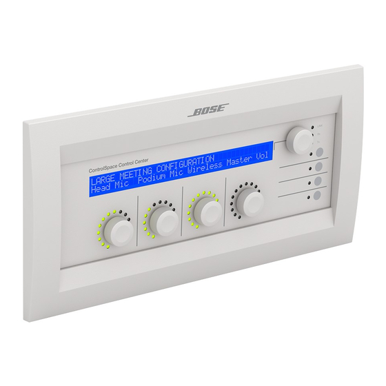
- Page 4 Introduction Introduction ® ™ The Bose ControlSpace CC-64 control center is an elegant, program- mable, networked controller that provides users with a simple and logical interface to their ControlSpace system. Because the controller is completely programmable, you can customize the ControlSpace system, making only certain controls available, and simplifying user interaction with the system.
- Page 5 Introduction Features • 2-line by 40-character backlit LCD • Sixteen Gain/Selector controls (four banks of four) - Four rotary encoders for changing the gain level or selecting Introduction scenes/sources - Each encoder includes a 15-segment LED array for indicating the control’s current level or state - The encoders feature push buttons for muting gain controls or making selections...
-
Page 6: Front Panel
Front Panel Front panel Introduction Functions 1. LCD 2. Preset/Scene selector Rotate to view presets. Push to select. Push and hold for 5 seconds to enter Custom mode. 3. Network link indicator 4. Network receive indicator 5. Network transmit indicator 6. -
Page 7: Installation
Installation Quick start What you will need: The following items are needed for most installations: - 5-gang electrical wall box Installation - UTP Cat-5 cable terminated with RJ45 plugs (standard Ethernet wiring) - Ethernet hub - Power supply (not included with the CC-64) WARNING: The product must be connected to a limited-power (<240VA) power supply. - Page 8 Connections Installing the wall box We recommend steel, 5-gang, masonry boxes for wall-mounting. Install the wall box so that it is flush or just below the surface of the finished wall. Select a place that is convenient for users. We suggest mounting the unit at eye level for optimal LCD viewing angle.
- Page 9 Connections Changing the power input jumpers Power can be supplied directly to the 2-terminal Phoenix connector or over the Ethernet cable. By default, the CC-64 is configured for power from the power connector. If you choose power over the Ethernet cable, remove the four screws on the rear cover and move the two jumpers as shown below.
- Page 10 Connections Wiring a power supply to the RJ45 plug The diagram below illustrates how to connect a power supply to inject power over the Ethernet connection. Connect the ground wire from the supply to the BROWN/white and WHITE/brown wires of the Cat-5 cable. Connect the Installation power wire from the supply to the BLUE/white and WHITE/blue wires of the Cat-5 cable.
-
Page 11: Troubleshooting
Troubleshooting • Ensure that power supply is wired correctly and plugged in. No power • Verify that the supply is DC and provides at least 300mA at 15V. • If supplying power over the Ethernet, check that jumpers behind the back panel are in the correct position. - Page 12 Reference Mounting cutout To mount the CC-64 in a blank rack panel, podium or other location where an electrical box is not practical, use the dimensions below as a guide for creating a cutout. DIP Switch Settings Warranty Power supply requirements Input voltage range: 15 to 24VDC Current requirements: 300mA (@9VDC) - 300mA (@23VDC) Dimensions...
-
Page 13: Warranty
We will repair or replace any defective parts within a reasonable period of time and free of charge. How you can obtain warranty service: 1. You can ship the system to either a Bose Service Agency or to Bose directly with a proof of purchase from an authorized dealer. Please: A. - Page 14 This Limited Warranty is fully transferable provided that the current owner furnishes the original proof of purchase from an authorized Bose dealer. This Limited Warranty is void if the label bearing the serial number has been removed or defaced.
- Page 15 Warranty...
- Page 16 ©2005 Bose Corporation, The Mountain, Framingham, MA 01701-9168 USA 285041 AM Rev.00...
Need help?
Do you have a question about the ControlSpace CC-64 and is the answer not in the manual?
Questions and answers