
Related Manuals for L3 comminications Trilogy ESI-2000

Summary of Contents for L3 comminications Trilogy ESI-2000
- Page 1 Pilot’s Guide for the Electronic Standby Indicator Model ESI-2000 Software Release 1.x Avionics Systems...
- Page 3 Pilot’s Guide Methods and apparatus disclosed and described herein have been developed solely on company funds of L-3 Communications Avionics Systems, Inc. No government or other contractual support or relationship whatsoever has existed which in any way affects or mitigates proprietary rights of L-3 Communications Avionics Systems, Inc.
- Page 4 Part 23/25 Fixed Wing Aircraft and Part 27/29 Rotorcraft. The Trilogy ESI-2000 replaces traditional electro-mechanical standby instruments and combines the information into a compact and easy to read 4” x 3” display. Its...
-
Page 5: Table Of Contents
Table of Contents Chapter 1 Description .................1-1 Introduction ....................1-1 Software Release ..................1-2 Specifications ....................1-3 Optional Equipment ..................1-6 Limitations ....................1-7 Display Elements ..................1-7 Attitude ......................1-7 Slip/skid Indicator ..................1-9 Indicated Airspeed ..................1-9 Altitude.......................1-13 Heading (Optional) ..................1-15 Battery .......................1-16 Chapter 2 Basic Operation .................2-1 Introduction ....................2-1 Menu Operation ...................2-1 Brightness Adjustment ................2-2... - Page 6 List of Illustrations Figure 1-1: ESI-2000 ................1-1 Figure 1-2a: MAG-3100................1-6 Figure 1-2b: MAG-3000 ................1-6 Figure 1-3: Attitude Elements ..............1-8 Figure 1-4: IAS Elements ............... 1-11 Figure 1-5a: IAS Awareness Bar Cues for Part 23 Using Vne ....1-11 Figure 1-5b: IAS Awareness Bar Cues for Part 23/25 Using Vmo ...1-12 Figure 1-5c: IAS Awareness Bar Cues for Part 27/29 ......1-12 Figure 1-6: Attitude Elements ..............1-14...
-
Page 7: Chapter 1 Description
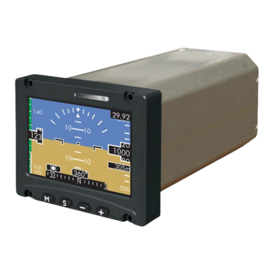
ESI-2000 Description CHAPTER 1 DESCRIPTIoN Introduction Refer to Figure 1-1. The ESI-2000 Electronic Standby Indicator is a panel mounted solid state instrument that provides a visual display of attitude (pitch & roll), slip/skid indicator, barometric corrected altitude, indicated airspeed, heading (optional), and battery indications. The indicator uses an Active Matrix Liquid Crystal Display (AMLCD) with a nominal diagonal size of 3.7 inches and a resolution of ¼... -
Page 8: Software Release
Description ESI-2000 Software Release The following software releases are available for the ESI-2000: • Release 1.0. Original Release. • Release 1.1. Provides a configuration option to choose airspeed units in either knots or miles per hour and incorporates an Airspeed Unit Descriptor that is shown on the display to show which unit type is being used. -
Page 9: Specifications
ESI-2000 Description Specifications PHySICAL Size: Bezel: 4.03” x 3.35” (10.24 x 8.51 cm) Chassis: 3-ATI Opening 7.66” (19.45 cm) Weight: 2.75 Lbs (1.25 kg) MAX Power: +28.0 VDC nominal, 10.0 W MAX (battery not charging) 22.0 W MAX (battery charging) +14.0 VDC (with external converter) Environmental: DO-160F... - Page 10 Description ESI-2000 Specifications (Continued) PERfoRMANCE Attitude: Accuracy: Error less than or equal to +/-3.0 degrees in pitch and roll with valid air data. Airspeed, Tape: Viewable Range: Release 1.0: (Part 23/25 Aircraft 0 to 450 kts) (Part 27/29 Rotorcraft 20 to 350 kts) Release 1.1 &...
- Page 11 ESI-2000 Description Specifications (Continued) oPERATIoN LIMITS Pitch, Roll, Yaw: All angles. Pitch, Roll, Yaw Rate +/- 100 degrees/second +/- 135 degrees/second (release 1.2) Altitude: Calibrated Range: -1,500 to 55,000 ft. / -457 to 16,764 m. BARO: 27.00 to 32.00 inches Hg. 914 to 1083 hPa or mb Altitude Rate: Up to ±...
-
Page 12: Optional Equipment
Description ESI-2000 Specifications (Continued) SCHEDULED Battery capacity meter requires automated MAINTENANCE: calibration periodically. Subject to requirements of FAA document CFR FAR Part 91.411. SERVICE LIfE: The indicator has unlimited service life. The battery has approximately 5 years of service life; provided that the procedures for maintenance are followed as detailed in the Battery Capacity Meter Calibration Procedure (see page 2-6) -
Page 13: Limitations
ESI-2000 Description Limitations When configured to operate with a magnetometer for heading reference input; the use of heading is not authorized to operate in the following polar regions due to magnetic field unsuitability: • North of 70° N latitude • South of 70°... -
Page 14: Figure 1-3: Attitude Elements
Description ESI-2000 Display Elements (continued) ATTITUDE (continued) Figure 1-3: Attitude Elements Roll Indicator (refer to Figure 1-3) The roll indicator consists of a roll scale and a roll pointer. The white scale lines are set at +/- 10, 20, 30, 45, and 60 degree tick marks with a downward white triangle representing the 0°... -
Page 15: Slip/Skid Indicator
ESI-2000 Description SLIP/SkID INDICATOR Slip/Skid Indicator (refer to Figure 1-3) The indicator has a black background with a white border. A Slip/Skid indicator ball is positioned in the center of the indicator scale between two vertical lines. The Slip/Skid indicator has a range of ±7°. The Slip/Skid indicator has two possible locations described below: •... - Page 16 Description ESI-2000 INDICATED AIRSPEED (continued) Airspeed Digital Readout (refer to Figure 1-4) The odometer styled IAS digital readout is located in the center of the airspeed tape and displays the current aircraft speed in knots. Release 1.0. The readout has a viewing range of 40 to 400 kts for Part 23/25 aircraft and 20 to 350 kts for Part 27/29 rotorcraft.
-
Page 17: Figure 1-4: Ias Elements
ESI-2000 Description INDICATED AIRSPEED (Continued) Figure 1-4: IAS Elements Figure 1-5a: IAS Awareness Bar Cues for Part 23 Aircraft using Vne Pilot’s Guide 1-11... -
Page 18: Figure 1-5C: Ias Awareness Bar Cues For Part 27/29
Description ESI-2000 INDICATED AIRSPEED (Continued) Figure 1-5b: IAS Awareness Bar Cues for Part 23/25 Aircraft using Vmo Figure 1-5c: IAS Awareness Bar Cues for Part 27/29 Rotorcraft 1-12 Pilot’s Guide... -
Page 19: Altitude
ESI-2000 Description ALTITUDE Barometric Pressure Window (refer to Figure 1-6) Located at the top right of the display screen. The value shown is used by the indicator to determine the current altitude. Configuration Option: The baro digits may be white, cyan, or green on a black background. -
Page 20: Figure 1-6: Attitude Elements
Description ESI-2000 ALTITUDE (Continued) Altitude Digital Readout (refer to Figure 1-6) The odometer styled digital readout is located in the center of the altitude tape and display’s the current baro-corrected altitude in feet above mean sea level (MSL). The readout can show a minimum of - 2000 feet and maximum of 56,000 feet. -
Page 21: Heading (Optional)
ESI-2000 Description HEADING (Optional) Heading Tape (refer to Figure 1-7) The heading tape is located at the bottom of the display. The tape moves left and right following the direction of the aircraft. The tape is a contiguous 360° linear scale. The tape is removed whenever the menu window is opened or if an attitude exceeding +/- 55 degrees of bank or +/- 55 degrees of pitch (unusual attitude). -
Page 22: Battery
Description ESI-2000 BATTERY Battery indicators and messages are located on the top-left side of the display. The indicators provide details on the general state of charge (SOC), availability of the battery for discharge or charge, and battery failure. The following table provides a brief description and examples of common battery indicators. - Page 23 ESI-2000 Description BATTERy DESCRIPTIoN INDICAToRS Charging Indicators Battery requires charging but is unable due to low or high temperature conditions. The discharge function of the battery continues to work depending on current SOC. Battery will begin to charge when temperature is within 0°C to 45°C (32°F to 113°F). NOTE: The interior of the ESI-2000 can be 10°C to 15°C (18°F to 27°F) warmer than the exterior.
-
Page 25: Chapter 2 Basic Operation
ESI-2000 Basic operation CHAPTER 2 BASIC oPERATIoN Introduction This chapter describes the user interface with the ESI-2000 electronic indicator that includes, but not limited to instructions on how to select menu items, change display settings, and view status information. Menu operation Refer to Figure 2-1. -
Page 26: Brightness Adjustment
Basic operation ESI-2000 BRIGHTNESS ADjUSTMENT (Refer to Figure 2-2) When selected in the menu window, the current brightness adjustment (0 to 100) is shown. Increase or decrease the brightness value by single press or holding the +/- buttons. The last change to the brightness level will be saved to memory and applied at power-up. -
Page 27: Figure 2-4: Alignment Screens (Not In Flight)
ESI-2000 Basic operation USER INITIATED ALIGNMENT (CONTINUED) NoTE Release 1.2. The heading tape and readout are available during alignment if the ESI-2000 is configured to receive external digital heading and heading data is valid. Alignment Screen for Part 23/25 Aircraft Alignment Screen for Part 27/29 Aircraft Figure 2-4: Alignment Screens (Not In Flight) Pilot’s Guide... -
Page 28: Baro Units Adjustment
Basic operation ESI-2000 BARO UNITS ADjUSTMENT (Refer to Figure 2-5) When selected in the menu window the current barometric unit is shown. • Press of the +/- buttons to change the baro unit selection from/to one of the following units: “in. Hg”, “hPa” or “mb”. •... -
Page 29: Status Screen
ESI-2000 Basic operation STATUS SCREEN (Refer to Figure 2-7) When selected in the menu window, pressing the Select S button opens the system status screen similar to Figure 2-8. Figure 2-7: Status Menu The status screen is only available in the menu list within the first 3 minutes after power is applied to the indicator and provides information about the indicator as well as any fault and installation problems detected during the Power-... -
Page 30: Battery Capacity Meter Calibration Procedure
Basic operation ESI-2000 BATTERY CAPACITY METER CALIBRATION PROCEDURE (Refer to Figure 2-9) A controlled discharge of the ESI-2000 is required annually to maintain accuracy of the capacity meter. Take the following into consideration before performing the calibration procedure: • Read the entire calibration procedure prior to starting. •... -
Page 31: Figure 2-9: Battery Calibration Menu
ESI-2000 Basic operation BATTERY CAPACITY METER CALIBRATION PROCEDURE (Continued) Take the following into consideration before performing the battery capacity meter calibration: • The battery SOC must be ≥ 90% before the calibration of the capacity meter can be accomplished. Refer to charging instructions in step 6. - Page 32 Basic operation ESI-2000 BATTERY CAPACITY METER CALIBRATION PROCEDURE (Continued) CAUTIoN THE AMBIENT TEMPERATURE OF THE ESI-2000 MUST REMAIN BETWEEN 10°C AND 25°C (50°F AND 77°F) DURING CALIBRATION. • If the battery SOC is not ≥ 90%, the following message is shown in the middle of the screen: Battery Requires Charge •...
-
Page 33: Chapter 3 Operating Instructions
ESI-2000 operating Instructions CHAPTER 3 oPERATING INSTRUCTIoNS Introduction This chapter describes the operation of the ESI-2000 indicator. Refer to Chap 1 for detailed information on display elements. Power on There is no power on/off switch on the ESI-2000. Depending on the aircraft use either the battery switches or avionics master switch to apply power. -
Page 34: Power Off
operating Instructions ESI-2000 PowER off (Refer to Figure 3-1) NoTE Manually shutting down the ESI-2000 conserves battery energy and is recommended in hot climate conditions. Depending on the aircraft, remove power to the ESI-2000 using either the avionics master switch, the battery switch, or dedicated ESI-2000 Power switch (as applicable). -
Page 35: System Identification
ESI-2000 operating Instructions SYSTEM IDENTIFICATION (Refer to Figure 3-2) The system identification splash screen display’s the following information: Company logo, software and firmware version information. After about seconds the indicator begins to align itself. Figure 3-2: Example of System ID Screen ALIGNMENT (Refer to Figure 3-3) During alignment indicated airspeed, altimeter, and barometric pressure begin displaying information while the attitude data is replaced with... -
Page 36: Normal Operation
operating Instructions ESI-2000 NORMAL OPERATION (Refer to Figure 3-4 a or b) Normal Operation of the ESI-2000 provides attitude (pitch and roll), barometric corrected altitude, metric altitude readout (optional), indicated airspeed, slip/skid indicator, airspeed awareness cues, and heading (optional) information. Figure 3-4a: Display Elements for Part 27/29 Aircraft Figure 3-4b: Display Elements for Part 23/25 Aircraft Pilot’s Guide... -
Page 37: Pre-Flight Instructions
ESI-2000 operating Instructions Pre-flight Instructions Prior to take off, it’s recommended the pilot do the following: MENU SETTINGS • Set brightness level. • Set barometric units displayed on Baro window. • Set barometric pressure. NoTE Press the Menu M button to open the menu window. Repeated pressing cycles the menu options. -
Page 38: In-Flight Screen Examples
operating Instructions ESI-2000 IN-FLIGHT SCREEN EXAMPLES NoTE The In-flight screen examples are typical of all software versions of the ESI-2000 with the exception of the airspeed units descriptor which was incorporated in software version 1.1. Figure 3-5 depicts a display configured with heading, rotating roll pointer, and airspeed configured for V (Part 23 aircraft). -
Page 39: Figure 3-7: Display Showing Menu Window
ESI-2000 operating Instructions IN-FLIGHT SCREEN EXAMPLES (Continued) Figure 3-7) depicts a display configured with heading, rotating roll pointer, metric altitude readout, the baro color configured green, and airspeed configured for V . (Part 23 aircraft). The display is shown with the baro menu window active causing the heading information to be removed. -
Page 40: Figure 3-9: Display Descending Left Bank
operating Instructions ESI-2000 IN-FLIGHT SCREEN EXAMPLES (Continued) Figure 3-9 depicts a display configured with heading, rotating roll pointer, airspeed configured for V (Part 23 aircraft), and gray colored tape areas. display shown descending while banking to the left with the airspeed awareness bar in the caution range. -
Page 41: Figure 1-1: Esi-2000
ESI-2000 operating Instructions IN-FLIGHT SCREEN EXAMPLES (Continued) Figure 3-11 depicts a display configured to show twin-engine airspeed set points, V and V (Part 23/25 aircraft) .The display is shown ascending with the airspeed awareness bar showing best rate of climb (V ) and minimum control speed ) with... -
Page 42: Errors And Invalidities
operating Instructions ESI-2000 ERRORS AND INVALIDITIES Rate Sensor Limit Exceeded (Refer to Figure 3-13) Release 1.0 & 1.1. If the ESI-2000 rate of motion (roll, pitch, or yaw) exceeds 100° per second, the heading and attitude data is removed from the display. - Page 43 ESI-2000 operating Instructions ERRORS AND INVALIDITIES (Continued) Cautionary Messages The cautionary messages functionality is only used by release 1.2. The messages are displayed when a overrate condition is detected from the ESI-2000 rate sensors and gives the pilot the option to perform or not perform an alignment.
-
Page 44: Figure 3-14: Airspeed Loss
operating Instructions ESI-2000 ERRORS AND INVALIDITIES (Continued) Indicated Airspeed Data Loss (Refer to Figure 3-14) If airspeed data is lost a red X replaces all the airspeed information and all attitude information is removed from the display; replaced with a “Attitude Fail”... -
Page 45: Figure 3-16: Altitude Loss
ESI-2000 operating Instructions ERRORS AND INVALIDITIES (Continued) Altitude Data Loss (Refer to Figure 3-16) If altitude data is lost a red X replaces all the altitude information and all attitude information is removed from the display; replaced with a “Attitude Fail”... -
Page 46: Figure 3-17: Align Hold
operating Instructions ESI-2000 ERRORS AND INVALIDITIES (Continued) Alignment Invalidity (Refer to Figure 3-17) During alignment the “Align Hold” message replaces the attitude information if the aircraft attitude is beyond straight and level flight for too long a period, or if attitude is in a heightened dynamic state. While the message is active and the ESI-2000 is configured for a magnetometer as the heading reference, the heading readout is removed and the heading tape is filled with a red X. -
Page 47: Figure 3-18: Heading Invalidity (No Mag Input)
ESI-2000 operating Instructions ERRORS AND INVALIDITIES (Continued) Magnetic Heading Invalidity with Message (Refer to Figure 3-18 & 3-19) If magnetic heading data becomes invalid during operation, the heading tape is filled with a red X and the heading digital readout is removed, replaced by either a “No Mag Input”... -
Page 48: Figure 3-20 Align Hold (No Mag Input)
operating Instructions ESI-2000 ERRORS AND INVALIDITIES (Continued) Magnetic Heading Invalidity, Align Hold and Message (Refer to Figure 3-20 & 3-21) Units with release 1.0 & 1.1, used on a Part 27/29 Rotorcraft only. If heading data is invalid prior to power being cycled or if the unit is re-aligned the “Align Hold”... -
Page 49: Figure 3-22: Heading Invalidity (No 429 Input)
ESI-2000 operating Instructions ERRORS AND INVALIDITIES (Continued) External Heading Source Invalidity (Refer to Figure 3-22, 3-23, 3-24) Release 1.2. If external heading source data is lost or becomes invalid during operation the heading tape is filled with a red “X” and the heading digital readout is removed, replaced by either a “No 429 Input”... - Page 50 operating Instructions ESI-2000 ERRORS AND INVALIDITIES (Continued) Figure 3-24: Heading Invalidity (429 Failed) 3-18 Pilot’s Guide...
-
Page 51: Chapter 4
ESI-2000 Troubleshooting CHAPTER 4 TRoUBLESHooTING NoTE Cycle Power Instructions: Remove input power from the ESI-2000 and shut down the backup power by pressing the M button and cycling through the menu options until the Shutdown menu is located. Press and hold the + button until the “SHUTTING DN”... - Page 52 Troubleshooting ESI-2000 Corrective Actions (continued) CoNDITIoN CAUSE/CoRRECTIVE ACTIoN Airspeed Awareness Indicates loss of airspeed configuration Color Band removed data. and SPD message Cycle power to the ESI-2000. displayed If airspeed configuration data is not re- stored, ESI-2000 may be defective. Have ESI-2000 checked by certified service center.
- Page 53 ESI-2000 Troubleshooting Corrective Actions (continued) CoNDITIoN CAUSE/CoRRECTIVE ACTIoN Battery not available Access the “Status Screen” from the menu as described in section 2 of this Pilot’s Guide. 1. If the “Batt Temp” temperature shown in the battery maintenance menu is >...
- Page 54 Troubleshooting ESI-2000 Corrective Actions (continued) CoNDITIoN CAUSE/CoRRECTIVE ACTIoN After successful One or more of the following conditions are detected. alignment the Head- 1. Heading data is invalid. ing digital readout is • If heading tape and readout do not removed and a red X become active, cycle power to the has replaced the digits ESI-2000.
- Page 55 ESI-2000 Troubleshooting Corrective Actions (continued) CoNDITIoN CAUSE/CoRRECTIVE ACTIoN Continued from • If the invalidity continues to be ob- served after power cycle there may previous page. be a problem with the Mag connec- tion or the Mag may be defective. Have Mag checked by certified service center.
- Page 56 Troubleshooting ESI-2000 Corrective Actions (continued) CoNDITIoN CAUSE/CoRRECTIVE ACTIoN Continued from previ- 2. If an “Inv 429 Input” message is shown above the heading tape, then ous page. invalid external heading input data is being received. • If the LRU providing external heading input data begins send- ing valid data, the message is removed and the heading tape and...
- Page 57 ESI-2000 Troubleshooting Corrective Actions (continued) CoNDITIoN CAUSE/CoRRECTIVE ACTIoN Attitude display ele- The Align Hold message is displayed when the unit is “Aligning” and one or ments replaced with more of the following conditions are de- “ALIGN HOLD” after tected. cycling power or re- 1.
- Page 58 Troubleshooting ESI-2000 Corrective Actions (continued) CoNDITIoN CAUSE/CoRRECTIVE ACTIoN Continued from previ- 3. For Part 27/29 aircraft - No Mag input signal is being detected. This is indi- ous page. cated by the heading digital readout being removed and a large red X in the middle of the heading tape.
- Page 59 ESI-2000 Troubleshooting Corrective Actions (continued) CoNDITIoN CAUSE/CoRRECTIVE ACTIoN System Status Screen: Have ESI-2000 system checked by certi- If one of the following fied service center. messages is shown: • Install Req. • Mag Swing Req. System Status Screen: ESI-2000 may be defective. Have ESI- If one of the following 2000 checked by certified service center.
-
Page 61: Record Of Important Information
APPENDIX A Record of Important Information Dealer Information Name______________________________________________________ Address____________________________________________________ City, State, Zip_______________________________________________ Telephone__________________________________________________ Equipment Information Date of Purchase____________________________________________ Installation Date_____________________________________________ Model Number______________________________________________ Part Number________________________________________________ Serial Number_______________________________________________ Mod Letter _________________________________________________ Release____________________________________________ Aircraft Information Aircraft Make_______________________________________________ Aircraft Model_______________________________________________ Serial Number_______________________________________________ N Number__________________________________________________ Register this product online at: www.l-3avionics.com/customercare/warrantyregistration Pilot’s Guide... -
Page 62: Installation Notes
Installation Notes (To be completed by the initial installer) oPTIoNS Tape Type: Gray Clear Baro Color: White Cyan Green Roll Pointer: Fixed Rotating Mag Installed: No (release 1.0 & 1.1) Ref Hdg Source: None ARINC 429 (release 1.2) keybd: ____ Altimeter Units: Ft &... - Page 63 Installation Notes (To be completed by the initial installer) ANGLES Panel Angle Pitch: _______ Roll: _______ Yaw: _______ (NOTE: Pitch, Roll, and Yaw panel angles must be determined at the time of initial installation.) MAG INSTALL Mounting Pitch: _______ Roll: _______ Yaw: _______ Wing Flex Airspeed No Comp: _______...
- Page 64 BATTERY SYMBOL QUICk REFERENCE BATTERY DESCRIPTION INDICATOR Not Shown No information needs to be conveyed to pilot Green More than 1 hour of operation remains Amber Less than 1 hour of operation remains Amber “X” Battery is not available to power unit (over temp or low battery voltage condition exists) Red “X”...
Need help?
Do you have a question about the Trilogy ESI-2000 and is the answer not in the manual?
Questions and answers