
Related Manuals for L3 comminications Trilogy ESI-1000

Summary of Contents for L3 comminications Trilogy ESI-1000
- Page 1 Pilot’s Guide for the Electronic Standby Indicator Model ESI-1000 Software Release 1.x and 2.0 communications...
- Page 3 Pilot’s Guide Methods and apparatus disclosed and described herein have been developed solely on company funds of L-3 Communications Avionics Systems, Inc. No government or other contractual support or relationship whatsoever has existed which in any way affects or mitigates proprietary rights of L-3 Communications Avionics Systems, Inc.
- Page 4 A Digital Revolution in Standby Instrumentation The Trilogy™ Electronic Standby Instrument (ESI) is a panel- mounted solid-state instrument that provides dependable backup for attitude, altitude and airspeed information for Part 23 Fixed Wing Aircraft and Part 27/29 Rotorcraft. The Trilogy ESI replaces traditional electro-mechanical standby instruments and combines the information into a compact and easy to read 4”...
-
Page 5: Table Of Contents
Table of Contents Chapter 1 Description ............1-1 Introduction ....................1-1 Software Releases and Aircraft Applications ..........1-2 Specifications ....................1-2 Optional Equipment ..................1-4 Limitations ....................1-4 Display Elements ..................1-5 Attitude ......................1-5 Slip / Skid.....................1-6 Indicated Airspeed ..................1-7 Altitude.......................1-10 Heading (optional) ..................1-12 Chapter 2 Basic Operation ........... 2-1 Introduction ....................2-1 Menu Operation ...................2-1 Display Brightness ..................2-2... - Page 6 List of Illustrations Figure 1-1: ESI-1000 (showing 2.0 software) ........1-1 Figure 1-2a: MAG-3100 ................1-4 Figure 1-2b: MAG-3000 ................1-4 Figure 1-3: Attitude Elements ...............1-5 Figure 1-4: IAS Elements..............1-7 Figure 1-5a: IAS Awareness Bar Cues for Part 23 with V ....1-8 Figure 1-5b: IAS Awareness Bar Cues for Part 23 with V ....1-9 Figure 1-5c:...
-
Page 7: Chapter 1 Description
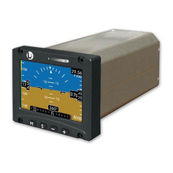
CHAptER 1 DESCRIPTIoN Introduction Refer to Figure 1-1. The ESI-1000 Electronic Standby Indicator is a panel mounted solid state instrument that provides a visual display of attitude (pitch & roll), slip/skid indicator (2.0 software only), barometric corrected altitude, indicated airspeed and magnetic heading (optional for Part 23 aircraft). -
Page 8: Software Releases And Aircraft Applications
Description ESI-1000 Software Releases and Aircraft Applications The following software releases are available for the ESI-1000: • Release 1.0. Part 23 Fixed Wing Aircraft only. • Release 1.1. Part 23 Fixed Wing Aircraft and Part 27/29 Rotorcraft. Incorporates specific airspeed awareness bar for part 27/29 Rotorcraft. - Page 9 ESI-1000 Description Specifications (Continued) Performance Attitude: Accuracy: Error less than or equal to 2.5 degrees in pitch and roll with valid air data. Airspeed, Tape: Viewable Range: 0 to 450 kts. Airspeed, Readout: Viewable Range: (Part 23 Aircraft) 40 to 400 kts. (Part 27/29 Rotorcraft) 20 to 350 kts Altitude: Viewable Range: -2,000 to 56,000 ft.
-
Page 10: Optional Equipment
Description ESI-1000 optional Equipment The MAG-3100 and MAG-3000 manufactured by L-3 Avionics Systems are self contained three-axis magnetometers that provides a three component measurement of the earth’s magnetic field. Refer to Figure 1-2 a & b. If the magnetometer option is used, heading is shown on a tape and digital readout at the bottom of the display. -
Page 11: Display Elements
ESI-1000 Description Display Elements ATTITUDE Attitude Background (refer to Figure 1-3) The attitude background is divided into an upper blue sky and lower brown ground with the horizon line located where the sky and ground backgrounds meet. The attitude background moves up/down and clockwise/counter-clockwise around the boresight of the aircraft reference symbol in relation to the pitch and roll of the aircraft. -
Page 12: Slip / Skid
Description ESI-1000 ATTITUDE (Continued) Roll Indicator (refer to Figure 1-3) The roll indicator consists of a roll scale and a roll pointer. The white scale lines are set at +/- 10, 20, 30, 45, and 60 degree tick marks with a downward white triangle representing the 0°... -
Page 13: Indicated Airspeed
ESI-1000 Description INDICATED AIRSPEED Airspeed Tape (refer to Figure 1-4) The IAS tape is located on the left side of the display. The tape scrolls up as aircraft speed decreases and scrolls down as aircraft speed increases. The tape has a viewing range of 0 to 450 kts, and tape viewing span of 60 kts. -
Page 14: Figure 1-4: Ias Elements
Description ESI-1000 INDICATED AIRSPEED (Continued) Figure 1-4: IAS Elements Figure 1-5a: IAS Awareness Bar Cues for Part 23 Aircraft using Vne Pilot’s Guide... -
Page 15: Figure 1-5C: Ias Awareness Bar Cues For Part 27/29
ESI-1000 Description INDICATED AIRSPEED (Continued) Figure 1-5b: IAS Awareness Bar Cues for Part 23 Aircraft using Vmo Figure 1-5c: IAS Awareness Bar Cues for Part 27/29 Rotorcraft Pilot’s Guide... -
Page 16: Altitude
Description ESI-1000 ALTITUDE Barometric Pressure Window (refer to Figure 1-6) Located at the top right of the display screen. The value shown is used by the indicator to determine the current altitude. Configuration Option: The baro digits may be white, blue, or green on a black background. -
Page 17: Figure 1-6: Attitude Elements
ESI-1000 Description ALTITUDE (Continued) Altitude Digital Readout (refer to Figure 1-6) The odometer styled digital readout is located in the center of the altitude tape and display’s the current baro-corrected altitude in feet above mean sea level (MSL). The readout can show a minimum of - 2000 feet and maximum of 56,000 feet. -
Page 18: Heading (Optional)
Description ESI-1000 HEADING (Optional) Heading Tape (refer to Figure 1-7) The heading tape is located at the bottom of the display. The tape moves left and right following the direction of the aircraft. The tape is a contiguous 360° linear scale and remains viewable when the display attitude is displaced up to a minimum of +/- 55 in pitch and roll. -
Page 19: Chapter 2 Basic Operation
CHAptER 2 BASIC oPERATIoN Introduction This chapter describes the user interface with the ESI-1000 electronic indicator that includes, but not limited to instructions on how to select menu items, change display settings, and view status information. Menu operation Refer to Figure 2-1. Pressing the Menu M button removes the heading tape and digital readout and opens the Menu window above the +\- buttons. -
Page 20: Display Brightness
Basic Operation ESI-1000 DISpLAy BRIGHtNESS (Refer to Figure 2-2) When selected in the menu window, the current brightness adjustment (0 to 100) is shown. Increase or decrease the brightness value by single press or holding the +/- buttons. The last change to the brightness level will be saved to memory and applied at power-up. -
Page 21: User Initiated Alignment
ESI-1000 Basic Operation USER INITIATED ALIGNMENT (Refer to Figure 2-3 and 2-4) When selected in the menu window, pressing the Start S button will force the indicator to re-align. The attitude will align within 1 minute if the aircraft is on ground and stationary. •... -
Page 22: Baro Units Adjustment
Basic Operation ESI-1000 BARO UNITS ADjUSTMENT (Refer to Figure 2-5) The Baro units adjustment is available only with SW 2.0. When selected in the menu window the current barometric unit is shown. • Press of the +/- buttons to change the baro value from/to one of the following units: “in. -
Page 23: Status Screen
ESI-1000 Basic Operation STATUS SCREEN (Refer to Figure 2-7) When selected in the menu window, pressing the Select S button opens the system status screen similar to Figure 2-8. Figure 2-7: Status Menu the status screen is only available in the menu list within the first 3 minutes after power is applied to the indicator and provides information about the indicator as well as any fault and installation problems detected during the Power-On Self Test. -
Page 25: Chapter 3 Operating Instructions
CHAptER 3 OPERATING INSTRUCTIONS Introduction This chapter describes the operation of the ESI-1000 indicator. Refer to Chap 1 for detailed information on display elements. Power on There is no power on/off switch for the ESI-1000. Depending on the aircraft use either the battery switches or avionics master switch to apply power. The indicator will transition through the following startup sequence: •... -
Page 26: System Identification
Operating Instructions ESI-1000 SYSTEM IDENTIFICATION (Refer to Figure 3-1) the system identification splash screen display’s the following information: Company logo, software and firmware version information. After about 15 seconds the indicator begins to align itself. Figure 3-1: Example of System ID Screen ALIGNMENT (Refer to Figure 3-2) During alignment indicated airspeed, altimeter, and barometric pressure begin displaying information while the attitude data is replaced with... -
Page 27: Normal Operation
ESI-1000 Operating Instructions NORMAL OPERATION (Refer to Figure 3-3 a, b, or c) Normal Operation of the ESI-1000 provides attitude (pitch and roll), barometric corrected altitude, indicated airspeed, airspeed awareness cues and magnetic heading (optional for Part 23 aircraft) information. In addition software release 2.0 provides a Slip/skid Indicator and a metric altitude readout (optional). - Page 28 Operating Instructions ESI-1000 NORMAL OPERATION (Continued) Figure 3-3c: Display Elements for Part 23 Aircraft with Software Release 2.0 Pilot’s Guide...
-
Page 29: Pre-Flight Instructions
ESI-1000 Operating Instructions Pre-Flight Instructions Prior to take off, it’s recommended the pilot do the following: MENU SETTINGS • Set brightness level. • Set barometric units displayed on Baro window. (SW Ver. 2.0 Only.) • Set barometric pressure. NoTE Press the Menu M button to open the menu window. Repeated pressing cycles the menu options. -
Page 30: In-Flight Screen Examples
Operating Instructions ESI-1000 IN-FLIGHt SCREEN EXAMpLES NoTE The following examples depict software releases (1.0, 1.1 and 2.0) used by the ESI-1000 and aircraft applications (Part 23 and Part 27/29) that the ESI- 1000 may be installed on. Differences are noted when applicable. Figure 3-4 depicts a display with 2.0 software configured with heading, rotating roll pointer, and airspeed configured for V (Part 23 aircraft). -
Page 31: Figure 3-6: Display Showing Menu Window
ESI-1000 Operating Instructions IN-FLIGHt SCREEN EXAMpLES (Continued) Figure 3-6 depicts a display with 2.0 software configured with heading, rotating roll pointer, metric altitude readout, the baro color configured green, and airspeed configured for . (Part 23 aircraft). The display is shown with the baro menu window active causing the heading information to be removed. -
Page 32: Figure 3-8: Display Descending Left Bank
Operating Instructions ESI-1000 IN-FLIGHt SCREEN EXAMpLES (Continued) Figure 3-8 depicts a display with 2.0 software configured with heading, rotating roll pointer, airspeed configured for V (Part 23 aircraft), and gray colored tape areas. The display is shown descending while banking to the left with the airspeed awareness bar in the caution range. -
Page 33: Figure 3-10: Display Showing
ESI-1000 Operating Instructions IN-FLIGHt SCREEN EXAMpLES (Continued) Figure 3-10 depicts a display with 1.x software configured to show twin- engine airspeed set points, V and V (Part 23 aircraft) .The display is shown ascending with the airspeed awareness showing best rate of climb ) and minimum control speed ) with critical... -
Page 34: Errors And Invalidities
Operating Instructions ESI-1000 ERRORS AND INVALIDITIES Rate Sensor Limit Exceeded (Refer to Figure 3-12) If the ESI-1000 rate of motion (roll, pitch, or yaw) exceeds 100° per second the heading and attitude data is removed from the display. When steady and level flight can be maintained, press the menu M button twice followed by pressing the... -
Page 35: Heading Data Loss
ESI-1000 Operating Instructions ERRORS AND INVALIDITIES (Continued) Heading Data Loss (Refer to Figure 3-15) Units with 1.0 and 2.0 software used on a Part 23 aircraft only. If heading data becomes invalid during operation the heading tape is filled with a red X and the heading digital readout is removed. -
Page 36: Heading Invalidity With Message
Operating Instructions ESI-1000 ERRORS AND INVALIDITIES (Continued) Heading Invalidity with Message (Refer to Figure 3-17 & 3-18) Units with 1.1 software only. If heading data becomes invalid during operation the heading tape is filled with a red X and the heading digital readout is removed, replaced by either a “No Mag Input”... - Page 37 ESI-1000 Operating Instructions Heading Invalidity, Align Hold and Message (Refer to Figure 3-19 & 3-20) Units with 1.1 software used on a Part 27/29 Rotorcraft only. If heading data is invalid prior power being cycled or if the unit is re- aligned the “Align Hold”...
-
Page 39: Chapter 4 Troubleshooting
ESI-1000 Troubleshooting CHAptER 4 TRouBLESHooTING Corrective Actions conDition caUse/correctiVe action Attitude or heading When aircraft returns to normal flight (straight and level) press the Menu M but- does not match primary ton twice and press the Select S button to flight display. - Page 40 Troubleshooting ESI-1000 Corrective Actions (continued) conDition caUse/correctiVe action SW Release 1.1 only. One or more of the following conditions are detected. After successful 1. Heading data is invalid. alignment the Head- • If the heading tape and readout do not become active, cycle power to ing digital readout is the ESI-1000.
- Page 41 ESI-1000 Troubleshooting Corrective Actions (continued) conDition caUse/correctiVe action SW Release 1.1 only The Align Hold message is displayed when the unit is “Aligning” and one or more of Attitude display ele- the following conditions are detected. ments replaced with 1. The pitch or roll angle of the unit is in a heightened dynamic state.
- Page 42 Troubleshooting ESI-1000 Corrective Actions (continued) conDition caUse/correctiVe action SW Release 1.0 and Heading data is invalid. 2.0 only. Heading digi- • If the heading tape and readout do tal readout is removed not become active, cycle power to and heading tape the ESI-1000.
- Page 43 ESI-1000 Troubleshooting Corrective Actions (continued) conDition caUse/correctiVe action System Status Screen: the ESI-1000 may be defective. Have ESI-1000 checked by certified service If one of the following center. messages appear: • Processor Fail • Memory Fail • Supply Fail • Sensor Fail •...
-
Page 45: Record Of Important Information
APPENDIX A Record of Important Information Dealer Information Name______________________________________________________ Address____________________________________________________ City, State, Zip_______________________________________________ Telephone__________________________________________________ Equipment Information Date of Purchase____________________________________________ Installation Date_____________________________________________ Model Number______________________________________________ Part Number________________________________________________ Serial Number_______________________________________________ Mod Letter_________________________________________________ Software Release____________________________________________ Aircraft Information Aircraft Make_______________________________________________ Aircraft Model_______________________________________________ Serial Number_______________________________________________ N Number_________________________________________________ Register this product online at: www.l-3avionics.com/customercare/warrantyregistration Pilot’s Guide... -
Page 46: Installation Notes
Installation Notes (To be completed by the initial installer) oPTIoNS Tape Type: Gray Clear Baro Color: White Blue Green Roll Pointer: Fixed Positive (Rotating, SW 2.0) Mag Installed: Keybd: ____ Altimeter Units: Ft & M AIRSPEED Part 23 Type V Part 23 Type V Part 27/29 Rotorcraft : _____... -
Page 47: Notes
Notes Pilot’s Guide... - Page 48 communications 0040-32000-01 Rev-E (10-20-2010) L-3 Communications Avionics Systems 5353 52 Street, S.E. Grand Rapids, MI USA 49512-9704 Telephone (800) 453-6600 International (616) 949-6600 www.as.l-3com.com...
Need help?
Do you have a question about the Trilogy ESI-1000 and is the answer not in the manual?
Questions and answers