
Related Manuals for ARRI M-Series ARRIMAX 18/12


Summary of Contents for ARRI M-Series ARRIMAX 18/12
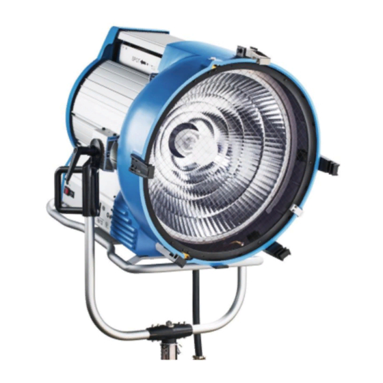
- Page 1 ARRIMAX 18/12 S E R V I C E M A N U A L Date: April 23, 2019 Supported Models L1.37950.B...
-
Page 2: Table Of Contents
Version History Version Author Change Note 03/2019 S. Papke Original version Table of Contents Version History ........................2 Table of Contents ....................... 2 Important Information......................3 Safety Instructions ......................3 General Safety Requirements for Operating Lamphead Systems ........ 3 Required Tools ........................4 Disassembling Order ...................... -
Page 3: Important Information
Please also refer to the Ordinance on Industrial Safety and Health as well as the relevant guidelines and regulations of your national Industrial Injuries Corporation (e.g. BGI 810-1, -3 and -4, BGV A1 for Germany; OSHA or ESTA for USA; etc.). Please refer also to our leaflet "Operating your ARRI Lamp heads safely" L5.70431.E... -
Page 4: Required Tools
b) Safety Requirements Concerning Electrical Danger » Please check the lamp head system and its electrical protection device before each use. » The faultless function of the power supply and protection system must be ensured before connecting the lamp head (e.g. grounding, circuit breaker). It might be necessary to install additional protection measures;... -
Page 5: Disassembling Order
Disassembling Order The graphic shows the order in which the components must be removed to ensure a proper repair. components which are not preceded by a further assembly group can be exchanged directly. Safety Switch Skid Cooling Protection Glass Lens Door Back Lamp Reflector... -
Page 6: Safety Switch Activator (Ssa)
Safety Switch Activator (SSA) Set the Focus to Spot. The reflector is now in position to open the lens door. Loosen 1 screw (1.5 mm Allen key) directly below the SSA. Do not remove. Now you can move the SSA forward or backwards to find the right adjustment. -
Page 7: Lens Door
Lens Door Hold the lens door and then loosen and remove the screw on the top (13mm ratchet.) Lift the bottom out and tilt the lens door to the front and slide out. To exchange/clean the glass or wire mesh remove 12 screw (Philips PH2.) 6 screws around the rim and 3 pairs (6) on the attachments. -
Page 8: Reflector: Replacement And Maintenance
Reflector: Replacement and Maintenance Remove 6 screws (PH2 Phillips.) Reach inside the reflector and remove as pictured. Inspection/Maintenance points. • Check if the reflector is dull or matt, specifically if it is matt towards the center. • Check the reflector center rim for signs of melting. -
Page 9: Back Housing
Back Housing Remove 10 screws (10 mm ratchet) 6 (black) screws three on each side and 4 shorter silver screws which are located on the top. Turn the lamphead around to access the screws in the back. Remove the 4 black screws (Philips PH2) on the bottom half. -
Page 10: Lamp Carriage Removal
Lamp Carriage Removal Remove 4 screws (Torx 20) as shown. Move the focus to flood and then you can access two additional screws (Torx 20.) ARRIMAX – Service Manual Page 10 of 20... - Page 11 Remove 2 screws (13 mm rachet) as shown. Tip: Screw them back to avoid losing them. ARRIMAX – Service Manual Page 11 of 20...
- Page 12 Remove lamp carriage assembly. ARRIMAX – Service Manual Page 12 of 20...
-
Page 13: Lamp Carriage Adjustment
Lamp Carriage Adjustment Position the lamp carriable assembly on the frame as shown. Install the 4 screws (Torx 20) without completely tightening them. Reinstall the HT cables (13 mm wrench.) Install 2 screws (Torx 20) on the side without completely tightening them. The focus must be set to flood. - Page 14 Attach the black plate on the front and slide it in to the reflector carriage as shown. Tighten 6 screws (Torx 20.) Open the lamp lock and remove the gauge and the black adjustment plate. When sliding the back housing back on, the two fins of the baffles must be inside the flood/spot baffle as shown.
-
Page 15: Lamp Cables
Lamp Cables After removing the lamp carriage remove the lamp cables by unscrewing the two PTFE (white bushing as seen in picture.) The longer cable is installed in the front and the short cable facing the back of the lamphead. ARRIMAX –... -
Page 16: Fan Cooling System & Maintenance
Fan Cooling System & Maintenance To access the cooling system for the reflector/lampholder (2 front fans) remove the lens door and reflector. Place the lampead face down with the skid facing you. See the two service doors to access the fans. Remove 4 screws (Phillips PH2) from the doors. -
Page 17: Remove Bottom Plate And Skid
Remove Bottom Plate and Skid Remove 4 screws (Ratchet 13 mm) to remove the skid. Remove 6 screws (Philips PH2.) 4 on the side and 2 in the middle. The on/off switch, hour counter and fan can be accessed from this point. Careful: The on/off switch and hour counter fan is attached to the cable. -
Page 18: Maintenance And Care
Burn marks or discoloration may be an indication for contact problems. We strongly recommend a replacement to avoid damage on the lamp head. Please contact your local ARRI service partner for more information about how to adjust the lamp socket correctly. - Page 19 ARRIMAX – Service Manual Page 19 of 20...
-
Page 20: Contact
The manufacturer disclaims liability for any damage to persons or properties which are caused by an inappropriate operation of the fixture. Those lie in the responsibility of the operator. Visit our homepage www.arri.com/service-lighting for downloads and software tools. ARRIMAX – Service Manual...
Need help?
Do you have a question about the M-Series ARRIMAX 18/12 and is the answer not in the manual?
Questions and answers