Do you have a question about the SR8000 Series and is the answer not in the manual?
Questions and answers
Richard
April 29, 2025
Replaced the blown MOSFETs but fault alarm cannot go out. What could be the cause?
1 comments:
Mr. Anderson
May 15, 2025
The fault alarm on a Rohde & Schwarz SR8000 Series could remain active after replacing the blown MOSFETs if:
1. The voltage supply is still outside tolerance (Supply Unit Status shows "Error"). 2. The FPGA was not loaded (signal processing not functioning). 3. The EEPROM has a CRC error (data inconsistency). 4. A PLL in the RF section is unlocked. 5. The CF card data could not be read correctly. 6. A replaced fuse blows again, indicating further internal faults. 7. The automatic circuit breaker trips again. 8. Damage exists in the power supply or connected circuits that were not repaired.
In such cases, the device may need to be taken out of service and replaced.
Summary of Contents for Rohde & Schwarz SR8000 Series
Page 1
Broadcasting Division System Manual ® R&S 
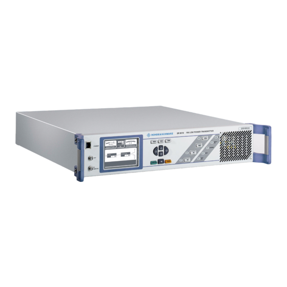
SR8000 – FM Transmitter VHF, Solid-State Low-Power All activities connected with installing, starting up, operating, maintaining, troubleshooting, and servicing the described system must be carried out by specialist technicians only. Printed in Germany 5300.9677.72 -4 - 0.1 -...
Page 4
KONFORMITÄTSERKLÄRUNG gemäß dem Gesetz über Funkanlagen und Telekommunikationsendeinrichtungen (FTEG) und der Richtlinie 1999/5/EG (R&TTE) Anhang V, zertifiziert durch die Benannte Stelle CETECOM ICT Services GmbH, Reg. Nr. Q812137N DECLARATION OF CONFORMITY in accordance with the Radio and Telecommunications Terminal Equipment Act (FTEG) and Directive 1999/5/EC (R&TTE Directive) Annex V, certified by the Notified Body CETECOM ICT Services GmbH Germany, Reg.
Page 5
KONFORMITÄTSERKLÄRUNG gemäß dem Gesetz über Funkanlagen und Telekommunikationsendeinrichtungen (FTEG) und der Richtlinie 1999/5/EG (R&TTE) Anhang V, zertifiziert durch die Benannte Stelle CETECOM ICT Services GmbH, Reg. Nr. Q812137N DECLARATION OF CONFORMITY in accordance with the Radio and Telecommunications Terminal Equipment Act (FTEG) and Directive 1999/5/EC (R&TTE Directive) Annex V, certified by the Notified Body CETECOM ICT Services GmbH Germany, Reg.
Page 10
Chapter 1 Safety CONTENTS 1 About this Manual ................4 2 Safety Instructions for Transmitter Systems and Equipment ..5 3 General Safety Instructions ............6 4 Special Hazard Information ............7 4.1 Hazards from AC Supply Voltage ..............7 4.1.1 AC Supply ....................7 4.1.2 Replacing Fuses ...................7 4.1.3 Emergency-Off System ................7 4.1.4 Opening the Transmitter ................8...
Chapter 1 Safety About this Manual This manual describes the R&S SR8000 transmitter. Structure The transmitter manual, which is the central and overarching part of the total documenta- tion, describes all the steps involved in installing, starting up, operating and maintaining a transmitter.
Chapter 1 Safety Safety Instructions for Transmitter Systems and Equipment ATTENTION! The safety regulations specified in this manual must always be complied with. The following points require special attention: All electrical installation and connection work must be carried out by appropriately skilled personnel only.
Chapter 1 Safety General Safety Instructions This section contains general safety instructions applying to all products manufactured or sold by Rohde & Schwarz. In accordance with IEC215 or EN60215, transmitter systems and their add-on equipment must be operated under the responsibility of qualified technicians only. All legal provisions must be observed as a prerequisite for operating radio equipment and systems.
Chapter 1 Safety Special Hazard Information Hazards from AC Supply Voltage All V > 30 V AC or V > 60 V DC voltages must be regarded as hazardous. When working on voltages constituting a shock hazard, appropriate steps must be taken to exclude all forms of risk.
Chapter 1 Safety 4.1.4 Opening the Transmitter If the transmitter is to be opened for mechanical and/or electrical work (such as cleaning, repairs etc) the transmitter must be disconnected from the AC supply. In the case of low power transmitters this is done by switching off and withdrawing the power plug. In transmitters that are hardwired to the AC supply, the five basic rules for working on electrotechnical equipment must be observed without fail: –...
Chapter 1 Safety Instances occurring in practice continue to show that a short circuit triggered by a metal Note hand tool causes severe burns. A short circuit causes an arc and the rated output of the power supply sets up continuous welding. Exercise the same amount of caution for measurements on low impedance supplies;...
Chapter 1 Safety Transmitters and instruments supplied by Rohde & Schwarz are shielded so that even in the immediate vicinity there is no danger from RF radiation when all RF lines are connected. The field strengths comply with the specifications contained in EU directive 1999/519/EC and the 26th ordinance to the German Federal Government's Emission Control Act of De- cember 16, 1996 (26.
Chapter 1 Safety The transmitters themselves must be operated in lightning protection zone III areas only (i.e. inside closed, lightning protected buildings). The antenna output is protected against overvoltage not exceeding 2 kV. Customers must ensure that the lightning protection fitted to their antenna systems is designed to prevent over-high voltages reaching the transmitter.
Chapter 1 Safety Parts containing BeO ceramics do not present adverse health effects if used as directed. However, improper handling can release BeO dust. BeO dust produces chronic pulmonary damage (berylliosis) and prolonged inhalation of high doses can cause poisoning with breathing impairment and subsequent death.
Page 20
Chapter 1 Safety Berylliumoxid-Staub Beryllium oxide dust Hazard symbol: ”skull and crossbones” Ensure that bags are disposed of in accordance with national waste disposal regulations. Devices containing BeO ceramics that have been unsoldered must be disposed of in the same manner. All the manufacturers of parts containing BeO ceramics who are known to Rohde &...
Broadcasting Division CHAPTER 2 DESIGN AND FUNCTION Printed in Germany 5300.9677.72 - 2.1 - EN-4...
Page 24
Chapter 2 Design and Function CONTENTS 1 Design and Function ............... 4 1.1 Mechanical Design ..................5 1.1.1 Mechanical Design: Base Unit ..............5 1.1.2 Mechanical Design: Separate Amplifier .............11 1.2 Connections ....................12 1.2.1 Rear Panel Connections: Base Unit ............12 1.2.2 Rear Panel Connections: Separate Amplifier ..........15 1.2.3 Front Panel Connections: Base Unit ............16 1.2.4 Front Panel Connections: Separate Amplifier ..........17 1.3 Elements on the Front Panel ...............17...
Chapter 2 Design and Function Design and Function The R&S SR8000 FM transmitter family is used for transmitting broadcast signals in band II (VHF). Depending on the configuration, individual transmitters are available in different power classes from 100 W to 2500 W. Name Power SR8010...
Chapter 2 Design and Function Fig. 3 Transmitter R&S SR8250A (R&S SR8130 + R&S VU813) Mechanical Design 1.1.1 Mechanical Design: Base Unit The transmitter contains the following modules: Mainboard with instrument interfaces, amplifier control unit, functional hardware of the parallel remote-control interface Amplifier with 100/250/500 or 1000 W (1300 W) Exciter board with computer kernel, display/keypad interfaces Black-and-white 1/4 VGA LC display on the transmitter front panel with a resolution of...
Page 27
Chapter 2 Design and Function Fig. 4 R&S SR8000 - block diagram 5300.9677.72 - 2.6 - EN-4...
Page 28
Chapter 2 Design and Function Fig. 5 View inside of the R&S SR8010 transmitter 1) Amplifier 2) Exciter board 3) Mainboard 4) Intake lattice (front) 5) Fans (2x) 6) AC supply input 7) Power supply (beneath intake lattice) 5300.9677.72 - 2.7 - EN-4...
Page 29
Chapter 2 Design and Function Fig. 6 View inside the R&S SR8025/SR8050 transmitter — amplifier side 1) Amplifier 2) Preamplifier cover 3) Harmonics filter cover 4) Fans (2x) 5300.9677.72 - 2.8 - EN-4...
Page 30
Chapter 2 Design and Function Fig. 7 View inside the R&S SR8100/SR8130 transmitter — amplifier side 1) Amplifier 2) Preamplifier cover 3) Harmonics filter cover 4) Fans (2x) 5300.9677.72 - 2.9 - EN-4...
Page 31
Chapter 2 Design and Function Fig. 8 View inside of the R&S SR8025/SR8050/SR8100 transmitter — exciter side 1) Exciter board 2) Mainboard 3) Fans (2x) 4) AC supply input 5) Power supply unit for output stage 6) Power supply unit for exciter 5300.9677.72 - 2.10 - EN-4...
Chapter 2 Design and Function Fig. 9 View inside of the R&S SR8130 transmitter — exciter side 1) Exciter board 2) Mainboard 3) Fans (2x) 4) AC supply input 5) Power supply unit for output stage (2x) 6) Power supply unit for exciter 1.1.2 Mechanical Design: Separate Amplifier The R&S VU813 amplifier, when used as a component of the R&S SR8250A transmitter,...
Chapter 2 Design and Function Fig. 10 View inside of the R&S VU813 amplifier — coupler side 1) Combiner 2) Processor board 3) Absorber board 4) Fans (2x) 5) AC supply input 6) Power supply unit for output stage (2x) 7) Power supply unit for instrument controller Connections 1.2.1...
Page 34
Chapter 2 Design and Function Fig. 12 Connections on rear panel of R&S SR8025/SR8050/SR8100 transmitter Fig. 13 Connections on rear panel of R&S SR8130 transmitter Connectors Connector Function X2 RF OUT Antenna connector X31; X32 Fan connections 1 and 2 X23A Code (coding plug) X23B INTERLOCK...
Page 35
Chapter 2 Design and Function Connector Function X13 PILOT OUT Pilot tone output X12 AUX1 (RDS) RDS input X21 AES/EBU (MPX) AES/EBU (digital signal) or MPX (analog signal) X11R RIGHT Analog audio (right channel) X11L LEFT (MPX) Analog audio (left channel) or MPX (analog signal) X6 ETHERNET Rear panel Ethernet connection Signal ground...
Chapter 2 Design and Function Auxiliary signals (AUX inputs) The RDS (AUX1) and AUX2 ports are provided with 50 Ω BNC connectors. Both AUX in- puts are of equal priority. Additional information such as RDS, DARC, TMC and so on can be fed in at these inputs.
Chapter 2 Design and Function 1.2.3 Front Panel Connections: Base Unit Fig. 15 Front panel connections (left: R&S SR8010; right: R&S SR8025/SR8050/SR8100/SR8130) Connectors Connector Function ETHERNET RJ-45 connector to local (detached) operation using PC TEST Test output (preconfigured using MPX) RF MONITOR RF monitor output from the onboard amplifier 5300.9677.72...
Chapter 2 Design and Function 1.2.4 Front Panel Connections: Separate Amplifier Fig. 16 Connections on front panel of R&S VU813 amplifier Connectors Connector Function RF MON COMBINER RF monitor output for the coupler output signal RF MON AMPLIFIER RF monitor output from the onboard amplifier Elements on the Front Panel 1.3.1 Input Screen...
Chapter 2 Design and Function 1.3.2 Function Keys and Displays: Base Unit Menu keys Fig. 18 Menu operation Meaning/function MENU Access to menu operation (activation from system overview); call a context menu (activation from menu) BACK Cancel an entered value if not confirmed with OK; go back one step in menu HOME Return from menu tree to system overview...
Chapter 2 Design and Function Meaning / function LOCAL Toggle between local and remote operation. The LED (yellow) indicates local operating status and means the instrument cannot now be oper- ated via the interfaces. RESET Reset general fault after problem corrected; the Fault LED goes off Switch transmission operation on (LED shows green) Switch off transmission operation (LED shows yellow);...
Page 41
Chapter 2 Design and Function Display Meaning LINK Displays the communication status on the CAN bus (LED shows green) Signals four different states: – LED flashes rapidly: No master – LED flashes slowly: Bus not operational – LED permanently on: Normal communication –...
Chapter 2 Design and Function Specifications RF output power Standalone instrument ......100/250/500/1000/1300 W Combination ......... 2500 W (2 x 1250 W) Dimensions Width ............ 420 mm (19“) Depth ............ R&S SR8010: 510 mm (excl. handles) R&S SR8025/SR8050: 590 mm (excl. handles) R&S SR8100/SR8130: 590 mm (excl.
Chapter 2 Design and Function MPX baseband signal RF output signal Forward power/reflected power of standalone instrument Forward power/reflected power of combined instrument Miscellaneous amplifier parameters Fan function Protection of Electrical System The following section describes the faults that can occur in the electrical system of the transmitter and how the electrical system is protected against these faults.
Chapter 2 Design and Function 2.1.2 Power Supply Fault (R&S SR8010) The transmitter includes a power supply unit. The exciter board and mainboard are supplied with power through a DC/DC converter with current-limited output. All lines carrying AC supply voltage and high current are covered to prevent touching (double insulation, sheathed conductor + shrink-on sleeve).
Chapter 2 Design and Function Fault Protection mechanism Function Damage between line filter Protected by primary fuses Primary fuse trips. and power supply unit Damage to power supply Protected by primary fuses Primary fuse trips. unit Damage between amplifier Current limited by amplifier power sup- Current limitation power supply unit and ampli- ply unit...
Chapter 2 Design and Function 2.1.5 Power Supply Fault (R&S VU813) The instrument has three power supply units. The instrument controller is supplied with power from an auxiliary power supply unit with current-limited output. All lines carrying AC supply voltage and high current are covered to prevent touching (double insulation, sheathed conductor+shrink-on sleeve).
Chapter 2 Design and Function Fault Protection mechanism Function Electrical connection of Capacitive coupling within RF ampli- No connection operating voltage to inner fier output circuit conductor of RF output Power reduction of FM transmitter with VSWR If the transmitter is operated with mismatched load at a VSWR > 1.5, the transmitter should not be shut down completely but instead should continue to operate with reduced power.
Chapter 2 Design and Function 2.1.8 Mechanical Loading The transmitter is a 19" unit. The weight of the various instruments can be found in the fol- lowing table (protection mechanism column). The table lists two categories of mechanical hazards: – Weight –...
Page 49
Chapter 2 Design and Function 5300.9677.72 - 2.28 - EN-4...
Chapter 3 Installation Equipment Supplied The equipment supplied with an R&S SR8000 transmitter includes the following items: – 1 R&S SR8000 – 1 manual (CD) – Safety instructions Optional – Power cable – Printed manual Please check that the above items are included in the equipment supplied. 5300.9677.72 - 3.4 - EN-4...
Chapter 3 Installation Cabling ATTENTION! Do not connect any devices to the AC supply until all cabling has been completed. AC Power Supply 2.1.1 Connecting Transmitter Ground ATTENTION! For safety reasons, the transmitter must be connected to the station's main ground termi- nal.
Chapter 3 Installation Fig. 3 Ground connection on rear panel of R&S SR8130 transmitter and R&S VU813 amplifier 1) R&S SR8130 2) R&S VU813 2.1.2 AC Supply The R&S SR8010/SR8025/SR8050 and SR8100 transmitters are operated by means of a low power device connecting cable. The current-carrying capacity is 10 A. The R&S SR8130 transmitter and the R&S VU813 amplifier are operated by means of a special 2.5 mm connecting cable.
Page 56
Chapter 3 Installation Fig. 5 Connections on rear panel of R&S SR8025/SR8050/SR8100 transmitter Fig. 6 Connections on rear panel of R&S SR8130 transmitter Connectors Connector Function X2 RF OUT Antenna connector X31; X32 Fan connections 1 and 2 X23A Code (coding plug) X23B INTERLOCK RF carrier loop, pin 1 + 9 X22A...
Page 57
Chapter 3 Installation Connector Function X13 PILOT OUT Pilot tone output X12 AUX1 (RDS) RDS input X21 AES/EBU (MPX) AES/EBU (digital signal) or MPX (analog signal) X11R RIGHT Analog audio (right channel) X11L LEFT (MPX) Analog audio (left channel) or MPX (analog signal) X6 ETHERNET Rear panel Ethernet connection Signal ground...
Chapter 3 Installation Auxiliary signals (AUX inputs) The RDS (AUX1) and AUX2 ports are provided with 50 Ω BNC connectors. Both AUX in- puts are of equal priority. Additional information such as RDS, DARC, TMC and so on can be fed in at these inputs. Rear Panel Connections (Separate Amplifier) Fig.
Chapter 3 Installation R&S SR8250A: Connecting Standalone Instruments Fig. 8 Connections between R&S SR8130 (above) and R&S VU813 (below) R&S SR8250A internal cabling No. in illustra- R&S SR8130 R&S VU813 Meaning of connection tion. X61 RF OUT SPLIT X61 RF IN SPLIT RF cable from exciter power splitter to R&S VU813 signal input X22B...
Chapter 3 Installation Front Panel Connections Fig. 9 Front panel connections (left: R&S SR8010; right: R&S SR8025/SR8050/SR8100/SR8130) Connectors Connector Function ETHERNET RJ-45 connector to local (detached) operation using PC TEST Test output (preconfigured using MPX) RF MONITOR RF monitor output from the onboard amplifier 5300.9677.72 - 3.11 - EN-4...
Chapter 3 Installation Front Panel Connections (Separate Amplifier) Fig. 10 Connections on front panel of R&S VU813 amplifier Connectors Connector Function RF MON COMBINER RF monitor output for the coupler output signal RF MON AMPLIFIER RF monitor output from the onboard amplifier 5300.9677.72 - 3.12 - EN-4...
Chapter 4 Putting into Operation CONTENTS 1 General Information ................. 4 1.1 Preparations ....................4 1.2 Requirements ....................4 1.3 Operating the Transmitter ................5 2 Putting a Transmitter into Operation ..........6 2.1 Preparing for Local Operation ...............6 2.2 Checking and Setting System and Operating Parameters ......6 2.2.1 Changing the User Type ................6 2.2.2 Entering Default Settings ................7 2.2.3 Configuring R&S SR8250A System .............7...
Chapter 4 Putting into Operation General Information Transmitters are put into operation via the transmitter graphical interface. Preparations Before you can put a transmitter into operation, it must first have been fully installed. Check the following list to ensure that all connections have been correctly made: Review whether the transmitter has been correctly installed and connected (modulation feed, remote-control interfaces).
Chapter 4 Putting into Operation 4. If necessary, set the transmitter to OFF in the Transmitter > Operation menu window . 5. If necessary, set the correct frequency in the Transmitter > Exciter > RF menu window. 6. Disconnect the transmitter from the power supply and reconnect the interlock loop. 7.
Chapter 4 Putting into Operation Putting a Transmitter into Operation Local operation of the transmitter includes all the main information calls for the system pa- rameters and their setting, complete with intuitive graphical menus. Remote operation via a web browser is possible only if a PC or notebook is connected to the front or rear panel of the transmitter.
Chapter 4 Putting into Operation 2.2.2 Entering Default Settings This is how you enter the basic settings for the transmitter. Select Transmitter > Setup > Common. The Common window opens. You can enter the following settings in the Common window: Selection Explanation Date...
Chapter 4 Putting into Operation 2. Switch Additional Amplifier to present. 3. Restart the system. The separate amplifier is then logged on and the software on the R&S SR8250A system is configured. 2.2.4 Configuring Transmitter Standby and Remote-Control Inter- face In the System menu window, you can configure an existing standby system and the parallel remote-control interface.
Chapter 4 Putting into Operation Selection Description Tx Mode Used to set a standby system (if available): – Standalone (single transmitter) – 1+1 (1+1 standby system) – n+1 (n+1 standby system) Tx Reserve A1 to A8, B (used to select the transmitter number in a 1+1 or n+1 standby system) Parallel IO Used to activate/deactivate the parallel remote-control interface of the...
Chapter 4 Putting into Operation Selection Description Rear Ethernet Manual settings should only be made in the offline mode (context menu: Edit Offline) and then activated with Submit Changes (context menu). IP Address IP address Subnet mask Subnet mask Gateway Entry of a gateway address (assigned by the network administrator).
Page 72
Chapter 4 Putting into Operation Entry/display Description State Displays the status of the channel concerned Channel 1 For setting the audio input and stereo mode for channel 1 (Primary) Possible selections: – AF Mono L – AF Mono R – AF Mono (L+R)/2 –...
Chapter 4 Putting into Operation Entry/display Description Selection For selecting the active channel Possible selections: – Ch.1 – Ch.2 – Auto (automatic input selection): The best available channel is selected according to the following priority: 1.) Ch.1 is OK. ⇒ switch to Ch.1 2.) Ch.2 is OK.
Chapter 4 Putting into Operation 2. Select the required settings. The table below explains the adjustable parameters: Setting item Description Pilot tone Setting of the deviation produced by the pilot tone for stereo Value range: 2 kHz through 10 kHz (default setting 7 kHz) Active (Pilot tone) Switches the pilot tone on and off (active only in stereo mode;...
Page 75
Chapter 4 Putting into Operation 2. Select the required settings. The table below explains the adjustable parameters. Setting item Description Nominal Deviation Sets the nominal deviation; a 500 Hz sinewave FM signal at nominal level is modulated with this deviation Value range: 40 kHz through 150 kHz (default setting 40 kHz) The nominal level is set in the Input >...
Chapter 4 Putting into Operation 2.3.3.1 Deviation and MPX Limiters The limiter is able to monitor both peak deviation and average modulation power (to ITU-R SM 1268-1). The modulation power is defined in ITU-R SM 1268-1 as follows: The modulation power is a floating average value for the last 60 s. It therefore takes 60 s from powering up before the correct modulation power is measured.
Chapter 4 Putting into Operation when music continuously alternates between loud and soft, and enables an announcer to speak over it. In MPX mode (input 2 or input 3) the MPX power limiter is always deactivated. In this case Note the external source must ensure compliance with the ITU recommendation.
Chapter 4 Putting into Operation Display Description On-Time If the input amplitude is continuously above the threshold during the set time interval On-Time, the input is considered to be OK. Value range: 1 s through 6000 s (default setting 5 s) Off-Time If the input amplitude is continuously below the threshold during the set time interval Off-Time, the input is considered not to be OK.
Chapter 4 Putting into Operation 2.3.4.3 Setting the Parameters for the AUX inputs (incl. RDS) 1. Select Transmitter > Exciter > Input > Data Input. The Data Input window opens. 2. Set the parameters as shown in the table below. The AUX inputs AUX1 and AUX2 have the same priority and identical characteristics.
Chapter 4 Putting into Operation 2.3.5 Setting the Transmission Frequency The transmission frequency is set to 97.5 MHz by default. The "Forward power" customer test point at the transmitter output (SMA female) is set to an output level of +7 dBm to 13 dBm at a nominal power of 97.5 MHz into 50 Ω. The frequency response is 6 dB/octave.
Chapter 4 Putting into Operation 2. Set the parameters as shown in the table below. Display/setting item Description Forward Power Present forward power of the transmitter Nominal Power Nominal power of the transmitter (cannot be modified) Actual Ref. Voltage Present value of the reference Voltage RF Warning Limit Warning threshold for the forward power referenced to nominal power.
Page 82
Chapter 4 Putting into Operation The output power and the percentage specified for Ref. Voltage are not proportional to Note one another; e.g. 80 % Ref. Voltage (90 % in the case of R&S SR8130 and R&S SR8250A) corresponds roughly to the power class of the transmitter, and 40 % (45 %) to around a quarter of it.
Chapter 4 Putting into Operation Completing Procedure for Putting Transmitter into Operation When the steps described in the above sections have been carried out the transmitter is ready to operate. Each transmitter receives a test report from the final testing department complete with measurement data for every quality parameter.
Page 84
Chapter 4 Putting into Operation 2. Check the status of the warning and error indicators.If a transmitter is ready to operate, no warnings or errors will be signaled. 3. Select Transmitter > Exciter > Status > Exciter FM Board. The Status > Exciter FM Board window opens. 4.
Chapter 4 Putting into Operation 7. Check the status of the warning and error indicators. 3.1.3 Checking the Output Stage Status Display 1. Select Transmitter > Output Stage > Status. The Output Stage > Status window opens. Note The available displays depend on whether the system has a separate amplifier (right- hand menu window) or not (lefthand menu window).
Page 86
Chapter 4 Putting into Operation These event memories should be cleared before the transmitter starts broadcasting. 1. Select Transmitter > Logbook > Summary. The Logbook > Summary window opens. 2. Select the Clear Logbook command in the context menu. The entries in all event memories are deleted. 5300.9677.72 - 4.25 - EN-4...
Chapter 4 Putting into Operation R&S NetCCU800 Setup for 1+1/N+1 Systems with R&S SR8000 Check the settings in the following menus of the R&S NetCCU800 Switchover Unit (NSU): – Switch over Unit > Setup > TX Setup > TX Ai (i = 1 to 8 according to the number of transmitters) –...
Page 90
Chapter 5 Operation CONTENTS 1 General Information ................. 5 1.1 Authorizations and Menu Levels ..............5 1.1.1 Authorizations ....................5 1.2 Local Operation ....................7 1.2.1 Operating structure ..................8 1.2.1.1 Navigation ......................8 1.2.1.2 Selecting and Editing Entries ................10 1.2.1.3 Context menu ....................11 1.3 Operation from a PC or via Remote Control ..........12 1.3.1 Installation and Configuration ..............13 1.3.2 Browser-Based Operation ................16...
Page 91
Chapter 5 Operation 2.6.4 Device Info > Boot Flash Menu Window ............39 2.6.5 Device Info > Processor Board Menu Window ...........40 2.7 Exciter Menu ....................40 2.7.1 Exciter > Status Menu ................40 2.7.1.1 Exciter > Status > Overview Menu Window ............. 40 2.7.1.2 Exciter >...
Chapter 5 Operation General Information Transmitters are operated via the transmitter's own graphical interface in the following ways: – Locally via the display and menu keys on the front panel – Via a web browser. If the unit is operated via the web browser of an attached PC/client computer, two modes are possible: –...
Chapter 5 Operation User profile Description Configuration Authorization to set basic transmitter parameters, e.g. Setup Maintenance Authorization to perform maintenance tasks, e.g. software updates Operation Authorization to make settings that directly affect transmitter operation Query Read-only authorization Guest Read-only authorization Config-Engl Authorization to set basic transmitter parameters, e.g.
Chapter 5 Operation Local Operation 1. Press the LOCAL key on the transmitter. The yellow LED to the left of the LOCAL key lights up. The display in the middle of the System Overview window changes from: Remote <--> Local 2.
Chapter 5 Operation Menu keys Fig. 2 Menu operation Meaning/function MENU Access to menu operation (activation from system overview); call a context menu (activation from menu) BACK Cancel an entered value if not confirmed with OK; go back one step in menu HOME Return from menu tree to system overview FUNCTION...
Page 96
Chapter 5 Operation 2. Select the required menu and confirm with OK. An overview of the selected menus opens. 1) Window and title bar for higher-level menus 2) Window and title bar for lower-level menus (submenus of the main menu selected in the window at the left) 3) Window and title bar with explanation of currently selected menu 4) The menu contains additional submenus (no arrow: direct access to a menu window) 3.
Chapter 5 Operation 1) The entry cannot be edited. 2) The entry can be edited. By using the MENUor FUNCTIONkey, you can call up a context menu from any position. Use the BACKkey to go back one step in the menu structure (even from the Help windows); you can also use BACK to cancel an entered value as long as you have not already con- firmed it with OK.
Chapter 5 Operation Editing entries In the editor, it is only possible to add new characters to existing characters. To insert char- acters at a certain position, you must first delete any existing characters from right to left and then enter new characters starting at the current cursor position. The editor is closed by selecting Enter text or Discard;...
Chapter 5 Operation The context menu can be called up from any position using the MENU FUNCTION key. The content-oriented commands are explained in the description for the respective menu window. The function-oriented commands are listed and described below: Command Explanation Change User Used to change the user profile...
Chapter 5 Operation Depending on their rights, logged-on users can monitor the transmitter in question or con- Note trol all of its functions. There is no difference between PC control and remote control with respect to this functionality. The transmitter contains the components for operation by PC or remote control as standard: Network port (10/100 MBit) 1.3.1 Installation and Configuration...
Page 101
Chapter 5 Operation Fig. 5 Entering IP address 2. From the context menu, select the Edit Offline mode. 3. Enter the parameters IP Address, Subnet Mask, and Gateway in the appropriate fields. 4. In the context menu, select Submit Changes. The changes will be made.
Page 102
Chapter 5 Operation 1. Select the Security tab. 2. For the Internet zone, select the Adapt Level option. 3. In the tree structure, go to Scripting > Scripting of Java applets and select the Enable option. Installing Java (Sun) JRE if necessary; checking and adapting settings 1.
Chapter 5 Operation 1.3.2 Browser-Based Operation The following entry screen appears after you have logged on: 1) System Overview: current transmitter status 2) Measure Values: display of power levels 3) Navigator: display and navigation through the transmitter menus 4) Display showing menu selected in Navigator 5) Control panel: elements for navigating the menu system and for displaying and editing the menu entries System Overview The System Overview window provides an overview showing the current status of the...
Page 104
Chapter 5 Operation Navigator The Navigator shows the menus of all system components. You can open the individual folders and menus by double-clicking with the mouse. The selected menus are displayed in the System Overview menu window. 1) Folder 2) Menu Menu window The menu window shows the menu selected in the Navigator window.
Page 105
Chapter 5 Operation 1) Items with double arrow symbol can be changed Control panel You can use the control panel to navigate the menu structure and menus and to change settings. You activate the individual control elements using the mouse or keyboard. 1) Used for switching between menu entries, for accessing editable values, and for entering numeric values;...
Chapter 5 Operation User Administration You can use the user administration facility to – Change user profiles (users and access rights) – Create new user profiles – Delete user profiles – Close active sessions The user administration facility is available in browser-based operation. The settings that you make in the user administration facility are (provided that no password is required) also valid for menu access via local operation.
Chapter 5 Operation Display Meaning Web browser The user ID and authorization permit operation via the web browser (Yes, No) Front panel The user ID and authorization permit local operation (Yes, No) Access right Authorization to access transmitter parameters Is Admin Additional user administration authorization (configuration, creation, and deletion of user profiles) The following users are factory-set.
Page 108
Chapter 5 Operation 2. Create the required user profile. Entry/selection Explanation Name: User ID (case-sensitive) Password: Must be at least 6 characters in length (case-sensitive) Retype password: Enter the password again (case-sensitive) Web browser The user ID permits menu access via the web browser Front panel The user ID permits menu access via the keys and display of the transmitter...
Chapter 5 Operation 3. Change the user profile in the way described under "Creating users". 4. Confirm your changes with Change User; clicking Reset discards your changes. Deleting users 1. Select the required user. 2. Select Delete selected user. The user is deleted. 1.4.2 Closing Active Sessions If you are logged on as Superuser, you can view detailed information on logged-on users...
Page 110
Chapter 5 Operation 4. Return to the previous browser window by clicking Show user list. 5300.9677.71 - 5.23 - EN-4...
Chapter 5 Operation Transmitter Menus You call the transmitter menus using the context menu. When you select Transmitter you can also access the Exciter and Output Stage menus. You are logged on by default under the authorization ID Operation. You can log on under a different authorization ID using Change User.
Page 112
Chapter 5 Operation Menu structure of transmitter Status Warning Fault Setup Common System Ethernet RS232 SNMP General Manager Alarmsinks BitBus Device Info Device Exciter FM Board Mainboard Boot Flash Processor Board Exciter Status Overview Exciter FM Board Analog Status Digital Status Input Analog Audio Digital Audio...
Chapter 5 Operation Menu structure of transmitter Automatic Input Modulation Deviation/Limiter Static Delay Outputstage Status Measurements Combiner Internal Amp External Amp Setup Limits Parameter Set a) You can also call the menu windows of the exciter and output stage directly from the main menu.
Chapter 5 Operation Display Explanation Operation Mode Status of transmission operation Input Ok: All activated inputs are OK. W: At least one activated input is not OK. Forward Power Ok: Transmitted power is OK. W: Transmitted power is not OK. Exc Warn There is an exciter sum warning.
Chapter 5 Operation Entry/display Description Operation Mode Setting for the operating status of the transmitter (On/Off) TX Sum Fault There is a general transmitter fault. TX Sum Warning There is a general transmitter warning. Reset on program off In the ON switch position, a Reset Fault is automatically triggered when the RF output is locked (Program = OFF).
Chapter 5 Operation 2.4.1 Summary Menu Window Fig. 6 Logbook > Summary window The following table explains the meaning of the columns: Column Explanation Consecutive number of entry Message Message Time Time at which the message was received Date Date on which the message was received The arrows in the second column have the following meaning: Arrow direc- Explanation...
Chapter 5 Operation Function Explanation Clear logbook Clears all entries in the current logbook. Note that it is not possible to clear individual entries. When you clear the complete logbook, the partial logbooks are also cleared. Restore logbook Restores the cleared entries in the current logbook. When you restore the complete logbook, the partial logbooks are also restored.
Chapter 5 Operation 2.5.2 Setup > System Menu Window In the System menu window, you can configure an existing standby system and the parallel remote-control interface. In the case of the R&S SR8130 base unit, you can also choose whether you intend the sys- tem to be operated with or without a separate amplifier.
Chapter 5 Operation – to a PC or laptop via the Ethernet interface on the front panel (cross cable), – to a LAN/WAN via the Ethernet interface on the rear panel. You can manually enter the parameters for the port on the front or rear panel to suit your requirements.
Chapter 5 Operation Function Description Baud rate For setting the baud rate as required (from 4800 to 115200) When using Bitbus: 19200 Data bits Number of data bits of the serial interface (5 to 8) Stop bits Number of stop bits of the serial interface (1 / 1.5 / 2) Parity For setting the parity (none/odd /even) 2.5.5...
Chapter 5 Operation Function Description Port SET/GET UDP port for SNMP SET/GET Default setting: 161 Inhibit Status Switch for message suppression in Local mode – Off: Traps (alarm messages) are sent in both operating modes (Remote and Local) – On: No traps are sent in Local mode but the alarms are stored; excep- tion: trap for Local Mode Default setting: Off If OIDs are polled with message suppression active, the return value is 0...
Chapter 5 Operation Function Description Community [1 … 5] Used to set the SNMP community string (a type of password) for a user group Default setting: "public" for read only (GET) and "broadcast" for read / write (SET) Case-sensitive! Enable Used to activate (On) or deactivate (Off) a community The Off setting is used for configuration purposes and for testing.
Chapter 5 Operation 2.5.6 Setup > BitBus Menu Window Use the BitBus menu window to activate and configure BitBus communication via Ethernet or RS-232-C. Setting item Description BitBus Protocol Switches BitBus communication on and off Remote Interface For choosing the remote-control interface for BitBus communication (Ethernet for X6, RS232 for X41) TCP Port Selects the port for the BitBus communication via Ethernet...
Chapter 5 Operation 2.6.1 Device Info > Device Menu Window The information in the Device menu window is used for troubleshooting purposes. If servic- ing is required, this information allows you to precisely identify the defective component and order a replacement. Display Explanation Part Number...
Chapter 5 Operation Display Explanation Part Number Stock number Variant Device variant Product index Product modification index Serial Number Serial number Production Date Date of production Operating hours Number of operating hours Power up cycles Number of times device has been switched on/off 2.6.3 Device Info >...
Chapter 5 Operation Display Description Part Number Stock number Model Device or module model Product index Product modification index Serial Number Serial number Production Date Date of production SW/FW Number Software/firmware stock number SW/FW Version Software/firmware version 2.6.4 Device Info > Boot Flash Menu Window The Boot Flash menu window displays information about the BIOS of the transmitter main- board.
Chapter 5 Operation 2.6.5 Device Info > Processor Board Menu Window The Processor Board menu window provides you with information about the processor board hardware and software in the R&S VU813 (for system R&S SR8250A). Display Description Part Number Stock number Model Device or module model Product index...
Page 128
Chapter 5 Operation Display Explanation Displays the status of the RF output: – Off There is no RF level at the exciter output since the RF output is not enabled ("manually" disabled) – Ok The RF level at the exciter output is OK –...
Page 129
Chapter 5 Operation Display Explanation Audio Ch2 Status of channel 2 (secondary audio input = standby): (the input type is set in the "Input > Automatic Input" menu window) – OK Channel 2 is functioning normally. – One Ch. Not OK In the case of Stereo or Mono L+R modulation, this status is displayed if just one of the two feeds for left and right is functioning normally while the other feed is faulty.
Chapter 5 Operation Display Explanation Sel. Audio Input Status of the currently active (= used) audio input (For details, see Input > Automatic Input menu window) The following states are displayed: – Type of audio input and stereo mode (e.g. AF Stereo or MPX Inp2) –...
Chapter 5 Operation Display Explanation FPGA Loaded Indicates whether it was possible to load the FPGA correctly: – FPGA loaded No fault – FPGA not loaded Signal processing is not functioning; if necessary, check the CF card; if no fault can be found, the device must be replaced. EEPROM Consistency of the module data: –...
Chapter 5 Operation Display Explanation Nominal Status display for the set nominal input amplitude Current Display of the peak value for the input amplitude during the last second; expressed in percentage and dBu terms Status Display of the current status; the possibilities are as follows: –...
Page 133
Chapter 5 Operation The states OK and Too Low are determined using the algorithm described in the section Note "Signal Monitoring at Analog Inputs". Display Explanation Nominal Status display for the set nominal input amplitude Current Display of the peak value for the input amplitude during the last second; shown as a percentage of the nominal input amplitude Status Indicates the current status as follows:...
Chapter 5 Operation Display Explanation Ch State Valid Indicates whether the decoded status displays of the AES channel are valid The following states are possible: – Off The input is not active. – Status Valid The input is active and the status of the AES channel is valid. –...
Page 135
Chapter 5 Operation Setting item Description Impedance Selection of the input impedance; possible settings: – 600 Ohm – >2 kOhm Level Setting the nominal input amplitude Value range (analog): -6 dBu through +12 dBu (default setting +6 dBu) Value range (MPX): -1 dBu through +16 dBu (default setting +6 dBu) Threshold Setting for the input amplitude threshold for monitoring The setting can be entered in two ways:...
Chapter 5 Operation Permissible input amplitude If the signal is greater than the nominal input amplitude, the internal limiter (if active) will limit the frequency modulated (FM) signal. If the signal has a level that is greater than 280% of the nominal input amplitude, the A/D converters are already overdriven and the signal will be clipped.
Chapter 5 Operation Setting item Explanation Threshold For setting the threshold of the digital input amplitude for monitoring The setting can be made in two ways: – as a percentage of the nominal input amplitude with the value range: 2% to 80% (default setting 5%) –...
Chapter 5 Operation The settings can be made separately for each of the three data inputs. Note The AUX inputs AUX1 and AUX2 have the same priority and identical characteristics. Typ- ically, the RDS signal is fed in at AUX1. AUX3 is only available internally in the transmitter. Display/entry Explanation AUX1 to AUX3...
Page 139
Chapter 5 Operation Entry/display Description Operating Mode For setting and displaying audio inputs and stereo mode Two different modulation types can be preselected. It is possible to switch between them manually or automatically. State Displays the status of the channel concerned Channel 1 For setting the audio input and stereo mode for channel 1 (Primary)
Page 140
Chapter 5 Operation Entry/display Description Channel 2 For setting the audio input and stereo mode for channel 2 (Secondary) Possible selections: – AF Mono L – AF Mono R – AF Mono (L+R)/2 – AF Stereo – AES Mono L –...
Chapter 5 Operation Entry/display Description Fail Delay For setting a time interval after which, in the event of a "No Input" warn- ing, the "No Input" fault message also has to be generated Only active when Report Type is set to Fault. a) Since switchovers are allowed for certain combinations only, the number of options offered for selection is limited depending on the settings for channel 2.
Chapter 5 Operation Setting item Description Pilot tone Setting of the deviation produced by the pilot tone for stereo Value range: 2 kHz through 10 kHz (default setting 7 kHz) Active (Pilot tone) Switches the pilot tone on and off (active only in stereo mode; the pilot tone is always off in mono mode) Selection of the signal preemphasis: 50 µs (default setting) or 75 µs Preemphasis...
Page 143
Chapter 5 Operation Setting item Description Nominal Deviation Sets the nominal deviation; a 500 Hz sinewave FM signal at nominal level is modulated with this deviation Value range: 40 kHz through 150 kHz (default setting 40 kHz) The nominal level is set in the Input > Analog Input menu for the analog inputs and/or in the Input >Digital Input menu for the AES/EBU input.
Chapter 5 Operation 2.7.4.1 Deviation and MPX Limiters The limiter is able to monitor both peak deviation and average modulation power (to ITU-R SM 1268-1). The modulation power is defined in ITU-R SM 1268-1 as follows: The modulation power is a floating average value for the last 60 s. It therefore takes 60 s from powering up before the correct modulation power is measured.
Chapter 5 Operation when music continuously alternates between loud and soft, and enables an announcer to speak over it. In MPX mode (input 2 or input 3) the MPX power limiter is always deactivated. In this case Note the external source must ensure compliance with the ITU recommendation. 2.7.5 Exciter >...
Chapter 5 Operation Display Description Ext. Ref. State Status indication of the external oscillator reference Options: – Off (the internal TCXO is used) – OK (the reference signal is present) – Not OK (the reference signal is not present or is defective) Ext.
Chapter 5 Operation Setting item Description Active Displays the active source for synchronizing the internal stereo coder pilot tone Options: – OFF – AES User Bits – AES Start Frame – Ext PPS Static Delay For setting the MPX signal delay Value range: 0 µs through 9 999 999.999 µs Step size: 1 ns Pilot Phase...
Chapter 5 Operation A further application is the virtually synchronous transmission of identical signals. This re- quires both Static Delay and Pilot Phase to be appropriately set. If the wrong values are used, the stereo channel crosstalk can deteriorate at the reception site, for example. Output Stage Menu You can use the Output Stage menu to enter settings in the RF power output stage and review their status.
Page 149
Chapter 5 Operation Display Description Reflection W: Antenna reflected power above the hardware limit Comms Output stage communication status With separate amplifier Display Description Op Mode Status of the transmission operation Forward Power Output power status Absorber Input Power Status of the absorber input (cut-off circuit when power dissipation too high) VSWR VSWR status on the internal/external amplifier and on the coupler output...
Chapter 5 Operation Display Description Comms Output stage communication status Power Supply Ok: External amplifier power supply is OK. 2.8.2 Outputstage > Measurements Menu 2.8.2.1 Outputstage > Measurements > Combiner Menu Window The Combiner menu window displays the measured values for the coupler in the optional separate amplifier.
Page 151
Chapter 5 Operation Display Description Internal Amplifier Forward Power Present output power Reflected Power Present reflected power VSWR VSWR (voltage standing wave ratio) Temperature Temperature at the amplifier heat sink Current Driver Current for the driver transistor Transistor 1 Current for the first output stage transistor Transistor 2 Current for the second output stage transistor Transistor 3...
Chapter 5 Operation 2.8.2.3 Outputstage > Measurements > External Amp Menu Window The External Amp menu window displays the measured values for an additional separate amplifier. The menu window is only displayed if a separate amplifier is connected. Display Description External Amplifier Forward Power Present output power...
Chapter 5 Operation Display Description Attenuator Control Control voltage for the PIN diodes ALC Control Control voltage for the output power 2.8.3 Output Stage > Setup Menu Window You can use the Setup menu window to set the transmitter output power and monitor power parameters.
Chapter 5 Operation Display/setting item Description Forward Power Present forward power of the transmitter Nominal Power Nominal power of the transmitter (cannot be modified) Actual Ref. Voltage Present value of the reference Voltage RF Warning Limit Warning threshold for the forward power referenced to nominal power. A warning is given if the value drops below the threshold.
Page 155
Chapter 5 Operation Entry/display Description Parameter Set Load Selecting a parameter set as the current parameter set; the currently loaded parameter set acts as an independent copy of the stored param- eter set. Save Saving the currently active settings to the chosen memory location. Copy From Selecting a parameter set that you wish to save to another memory loca- tion.
Page 156
Chapter 5 Operation Entry/display Description Names Parameter Set 1 Name to describe the parameter set (e.g. intended use) Parameter Set 2 See above Parameter Set 3 See above Parameter Set 4 See above Parameter Set 5 See above Parameter Set 6 See above Parameter Set 7 See above...
Page 161
Chapter 6 Maintenance Software Update Software updates for the transmitter are intended to improve performance and to retrofit op- tions. Requirements To perform a software update the following are required: PC or network client with MS Windows XP operating system or higher Update program (on CD-ROM) Ethernet connection between the transmitter and the PC via RJ-45 (cross cable) For communication to operate, the network ports between the transmitter and the PC must...
Page 162
Chapter 6 Maintenance 4. Double-click on the icon to start the update process. The start window of the R&S Software Distributor will open. 5. Select Remote Installation and confirm with Next. The available software updates will be displayed. 5300.9677.72 - 6.5 - EN-4...
Page 163
Chapter 6 Maintenance 6. Confirm the choice of SR8000 by clicking on Next. The R&S Software Distributor searches the network for compatible transmitters. The program window displays the message "Searching for devices...". The transmitters found are then listed. If the search fails, try disabling all firewalls between the PC and transmitters. Note 7.
Page 164
Chapter 6 Maintenance 9. At the end of the procedure, go to Report to call the report on the completed update. 10.Use Close to close the report window and use Cancel to close the R&S Software Dis- tributor. The transmitter carries out a reboot. 1.2.1 On Rebooting On the initial rebooot, do not switch off the transmitter in any circumstances until the system...
Page 165
Chapter 6 Maintenance The software version number can also be found on the browser login page. Note 5300.9677.72 - 6.8 - EN-4...
Page 169
Chapter 7 Troubleshooting Information The "Troubleshooting" chapter will be compiled later. 5300.9677.72 - 7.4 - EN-4...
Page 170
Broadcasting Division CHAPTER 8 SERVICE Printed in Germany 5300.9677.72 - 8.1 - EN-4...
Page 172
Chapter 8 Service CONTENTS 1 Necessary Tools and Test Equipment ........... 4 2 Removable Transmitter Components ..........5 3 Replacing Fan .................. 6 3.1 Removing the Fan ..................6 3.1.1 R&S SR8010 ....................6 3.1.2 R&S SR8025/SR8050/SR8100/SR8130/VU813 ..........7 3.2 Installing the Fan ....................9 4 Replacing Fuses on the Power Supply ........
Chapter 8 Service Necessary Tools and Test Equipment Depending on the service work to be performed, you will require the following tools: – Torx screwdriver, size 8 and 10 – Flat-tipped screwdriver – Side cutting pliers 5300.9677.72 - 8.4 - EN-4...
Chapter 8 Service Removable Transmitter Components You can remove and replace the following transmitter components if errors occur. Fuse Instruments R&S SR8130 and R&S VU813 are fitted with an automatic circuit breaker which can be switched back on if necessary by pressing a button. 5300.9677.72 - 8.5 - EN-4...
Chapter 8 Service Replacing Fan Two fans for cooling the transmitter are located on the rear panel of the transmitter, where they are easily accessible from outside. Removing the Fan 3.1.1 R&S SR8010 1. Undo the cable clamp (Torx screwdriver, size 8) and cut through the cable tie. Fig.
Chapter 8 Service Fig. 2 Removing connector of faulty fan 3. Unscrew the fuse block (if fitted) using a Torx screwdriver (size 10). 4. Slide the faulty fan upward and pull the fan out. 5. Pull the fan shroud off the removed fan. The fan shroud is not changed;...
Page 177
Chapter 8 Service Fig. 3 Disconnecting connector 3. Unscrew the fuse block using a Torx screwdriver (size 10). Fig. 4 Unscrewing fuse block 4. Slide the faulty fan upward out of the mounting holes and pull the fan out. 5300.9677.72 - 8.8 - EN-4...
Chapter 8 Service Fig. 5 Attachment of fan at rear of unit 1) Mounting holes 2) Fan shroud 5. Pull the fan shroud off the removed fan. The fan shroud is not changed; it is fitted to the replacement fan. Installing the Fan Replace the fan by proceeding in the reverse order and then cable it.
Chapter 8 Service Replacing Fuses on the Power Supply R&S SR8010 Two fuses are fitted in the line filter below the AC supply connector of the transmitter. The fuses can be accessed from outside at the rear of the transmitter. DANGER! Risk of electric shock! De-energize the unit before removing the fuses.
Chapter 8 Service Fig. 7 Pulling out fuse holder complete with fuses 3. Pull out the fuses and replace them with new ones. Only use replacement fuses that correspond to the type, tripping current, and tripping Note characteristic specified at the AC supply input. Fig.
Page 181
Chapter 8 Service DANGER! Risk of electric shock! De-energize the unit before removing the fuses. 1. To unlock the fuse holder, turn the screw 90° counterclockwise. Fig. 9 Unlocking fuse holder 2. Remove the fuse holder complete with fuse. 5300.9677.72 - 8.12 - EN-4...
Page 182
Chapter 8 Service Fig. 10 Pulling out fuse holder complete with fuse 3. Pull out the fuse and replace it with a new one. Note Only use replacement fuses that correspond to the type, tripping current, and tripping characteristic specified at the AC supply input. Fig.
Chapter 8 Service Switching on the Automatic Circuit Breaker R&S SR8130/VU813 The rear panels of the instruments are fitted with an automatic circuit breaker. If this auto- matic line fuse trips, a safety button pops up. Press this safety button to switch the circuit breaker back on. Fig.
Chapter 9 Appendix 1.1.3 RF (X7) – RF Test Output FM: SMA Connector Signal name Direction Value range Contact Remarks 50 Ω TEST_OUT_MON Output +7 dBm to 13 X7.1 87.50 MHz to 108.00 MHz Two way X7.2 Interfaces on the Rear Panel 1.2.1 X1 –...
Chapter 9 Appendix Signal name Direction Value range Contact Remarks Input Ethernet X6.3 n.c. X6.4 n.c. X6.5 Ethernet X6.6 n.c. X6.7 n.c. X6.8 1.2.3 X23A – Code: D-SUB Connector, 9-Pin Signal name Direction Value range Contact Remarks Code Bit 0 Input X23A.1 Code Bit 1...
Chapter 9 Appendix Signal name Direction Value range Contact Remarks LOOP+ Two way Open!⎝ RF loop open X23B.9 Internal to 0V FLT LOOP of Connection to SU800 board LOOP-!⎝ RF loop closed 1.2.5 X22A – Remote-Control Interface for Commands/Messages: D-SUB connector, 25-Pin Male Signal name Direction Value range...
Chapter 9 Appendix Signal name Direction Value range Contact Remarks Message 10 Input X22A.20 Return line for message 10 Common Message 10 NO Output X22A.21 Local mode (NO contact) contact Message 10 NC Output X22A.22 Remote mode (NC contact) contact Message 11 NO Output X22A.23...
Chapter 9 Appendix Signal name Direction Value range Contact Remarks Two Way X22B.12 Ground Two Way X22B.13 Ground Two Way X22B.14 Ground SHUT_DOWN Input Logic 5 V X22B.15 High: Fault Int.pullup from +5 AMPL_ON Output Logic 5 V (from X22B.16 High: Amplifier ON, refer- exciter) enced to GND...
Chapter 9 Appendix 1.2.8 X11L – AF Input Left (Alternative MPX): XLR Connector Signal name Direction Value range Contact Remarks Audio IN 2 + Input Adjustable left for X11L.2 Balanced or unbalanced, selectable 600 Ω or 40 kHz deviation: ≥ 2000 Ω -6 dBu to 12 dBu MPX: +5 dBu to +7 Audio IN 2 -...
Chapter 9 Appendix 1.2.11 X13 – Output Pilot: BNC Signal name Direction Value range Contact Remarks at ≥ 1000 Ω PILOT_OUT Output 1 Vpp into 1 kΩ X13.1 ±0.1 V Bidirect. X13.2 1.2.12 X14 – AUX2 Input (BNC) Signal name Direction Value range Contact...
Chapter 9 Appendix 1.2.15 X5 – GPS Antenna (BNC, Reserved) Signal name Direction Value range Contact Remarks 50 Ω GPS_ANT Input System antenna sig- X5.1 BNC Socket Two way X5.2 1.2.16 X2 – RF Output FM: N or 7/16 Connector Signal name Direction Value range...
Page 196
Chapter 9 Appendix Signal name Direction Value range Contact Remarks X32.4 Unused 5300.9677.72 - 9.13 - EN-4...
Need help?
Do you have a question about the SR8000 Series and is the answer not in the manual?
Questions and answers
Replaced the blown MOSFETs but fault alarm cannot go out. What could be the cause?
The fault alarm on a Rohde & Schwarz SR8000 Series could remain active after replacing the blown MOSFETs if:
1. The voltage supply is still outside tolerance (Supply Unit Status shows "Error").
2. The FPGA was not loaded (signal processing not functioning).
3. The EEPROM has a CRC error (data inconsistency).
4. A PLL in the RF section is unlocked.
5. The CF card data could not be read correctly.
6. A replaced fuse blows again, indicating further internal faults.
7. The automatic circuit breaker trips again.
8. Damage exists in the power supply or connected circuits that were not repaired.
In such cases, the device may need to be taken out of service and replaced.
This answer is automatically generated