Table of Contents
Advertisement
Available languages
Available languages
Advertisement
Table of Contents

Subscribe to Our Youtube Channel
Related Manuals for MSI 790GX-G65 Series


Summary of Contents for MSI 790GX-G65 Series
- Page 1 790GX-G65 Series MS-7576 (V1.X) Mainboard G52-75761X3...
-
Page 2: Trademarks
Alternatively, please try the following help resources for further guidance. Visit the MSI website for FAQ, technical guide, BIOS updates, driver updates, an d ot h er i n f orm at i on: h t t p: / / g l o ba l . -
Page 3: Safety Instructions
Safety Instructions Always read the safety instructions carefully. Keep this User’s Manual for future reference. Keep this equipment away from humidity. Lay this equipment on a reliable flat surface before setting it up. The openings on the enclosure are for air convection hence protects the equip- ment from overheating. -
Page 4: Fcc-B Radio Frequency Interference Statement
FCC-B Radio Frequency Interference Statement T h is eq uip men t h as been tested and found to c omply with the limits for a Class B digital device, pursuant to Part 15 of the FCC Rules. These limits are designed to provide reasonable protection against harmful interference in a residential installation. -
Page 5: Weee (Waste Electrical And Electronic Equipment) Statement
WEEE (Waste Electrical and Electronic Equipment) Statement... -
Page 8: Table Of Contents
CONTENTS Copyright Notice ......................ii Tradema rks ........................ii Revision History ......................ii Technical Support ...................... ii Safety Instructions ....................iii FCC-B Radio Frequency Interference Statement ..........iv WEEE (Waste Electrical and Electronic Equipment) Statement ....... v English ........................En-1 Mainboard Specifications ................. - Page 9 Connecteur d’alimentation ................Fr-10 Panneau arrière ....................Fr-11 Connecteurs ..................... Fr-13 Boutons ......................Fr-20 Slots ........................Fr-21 Interrupteur ....................... Fr-22 Réglages BIOS ....................Fr-28 Information de Logiciel ..................Fr-36 Русский ........................Ru-1 Характеристики ....................Ru-2 Руководство по размещению компонентов ..........Ru-4 CPU (Центральный...
-
Page 10: English
790GX-G65 Series User’s Guide English En-1... -
Page 11: Mainboard Specifications
® - Supports AMD Phenom II X4/ X3 and Athlon X4 /X3/ X2 processors in the AM3 package. (For the latest information about CPU, please visit http://global.msi.com.tw/index.php?func=cpuform2) HyperTransport - HyperTransport 3.0 up to 5.2GT/s Chipset ® - North Bridge: AMD 790GX / 780G chipset ®... - Page 12 Floppy - 1 floppy port - Supports 1 FDD with 360KB, 720KB, 1.2MB, 1.44MB and 2.88MB Connectors Back panel - 1 PS/2 port - 1 Optical S/PDIF-Out port - 1 VGA port - 1 DVI-D port - 1 HDMI port - 1 1394 port (optional) - 6 USB 2.0 ports - 1 eSATA port...
-
Page 13: Quick Components Guide
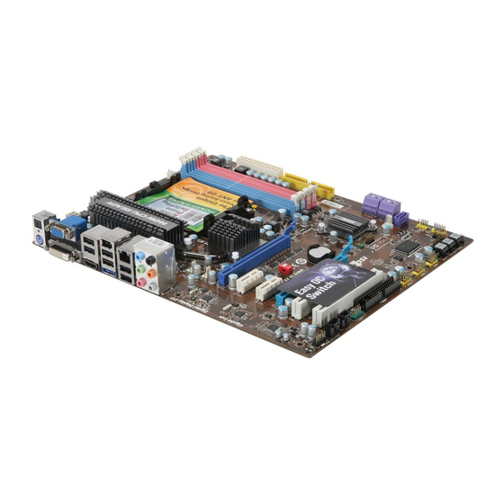
M S-7576 M ainboard Quick Components Guide DDR3, En-8 CPU, En-5 CPUFAN1, PWR1, En-10 En-15 JPWR1, En-10 Back Panel I/O, En-11 IDE1, En-13 SYSFAN1/2, OCSWITCH1, En-15 En-21 SYSFAN3, En-15 PCIE, SATA1~5, En-22 En-14 JFP2, En-18 JFP1, En-18 PCI, JTPM1, En-17 En-27 JCOM1, En-17 JCI1, En-15... -
Page 14: Cpu (Central Processing Unit
W hen you are installing the CPU, make sure to install the cooler to prevent overheating. If you do not have the CPU cooler, consult your dealer before turning on the computer. For the latest information about CPU, please visit http://global.msi.com.tw/index. php?func=cpuform2 Important Overheating Overheating will seriously damage the CPU and system. - Page 15 M S-7576 M ainboard CPU & Cooler Installation W hen you are installing the CPU, make sure the CPU has a cooler attached on the top to prevent overheating. Meanwhile, do not forget to apply some thermal paste on CPU before installing the heat sink/cooler fan for better heat dispersion. Follow the steps below to install the CPU &...
- Page 16 5. Position the cooling set onto the re- 6. Then press down the other end of tention mechanism. the clip to fasten the cooling set on the top of the retention mechanism. Hook one end of the clip to hook first. Locate the Fix Lever and lift up it .
-
Page 17: Memory
M S-7576 M ainboard Memory These DIMM slots are used for installing memory modules. For more information on compatible components, please visit http://global.msi.com. tw/index.php?func=testreport DDR3 240-pin, 1.5V 48x2=96 pin 72x2=144 pin Dual-Channel: Channel A in SKYBLUE; Channel B in PINK... - Page 18 Installing Memory Modules 1. The memory module has only one notch on the center and will only fit in the right orientation. 2. Insert the memory module vertically into the DIMM slot. Then push it in until the golden finger on the memory module is deeply inserted in the DIMM slot. The plastic clip at each side of the DIMM slot will automatically close when the memory module is properly seated.
-
Page 19: Power Supply
M S-7576 M ainboard Power Supply ATX 24-Pin Power Connector: JPWR1 This connector allows you to connect an ATX 24-pin power supply. To connect the ATX 24-pin power supply, make sure the plug of the pin 13 power supply is inserted in the proper orientation and the pins are aligned. -
Page 20: Back Panel
Back Panel 1394 Port RS-Out Line-In (optional) Optical USB Ports S/PDIF-Out VGA Port Line-Out CS-Out PS/2 port DVI-D Port HDMI Port eSATA USB Ports SS-Out Port Optical S/PDIF-Out This S/PDIF (Sony & Philips Digital Interconnect Format) connector is provided for digital audio transmission to external speakers through an optical fiber cable. - Page 21 M S-7576 M ainboard USB Port The USB (Universal Serial Bus) port is for attaching USB devices such as keyboard, mouse, or other USB-compatible devices. The standard RJ-45 LAN jack is for con- Activity Indicator Link Indicator nection to the Local Area Network (LAN). You can connect a network cable to it.
-
Page 22: Connectors
Connectors Floppy Disk Drive Connector: FDD1 This connector supports 360KB, 720KB, 1.2MB, 1.44MB or 2.88MB floppy disk drive. FDD1 IDE Connector: IDE1 This connector supports IDE hard disk drives, optical disk drives and other IDE devices. IDE1 Important If you install two IDE devices on the same cable, you must configure the drives separately to master / slave mode by setting jumpers. - Page 23 M S-7576 M ainboard Serial ATA Connector: SATA1~5 This connector is a high-speed Serial ATA interface port. Each connector can con- nect to one Serial ATA device. SATA4_5 SATA1 SATA2_3 Important 1. SATA5 only supports RAID and AHCI mode (does not support IDE mode) 2.
- Page 24 Fan Power Connectors: CPUFAN1, SYSFAN1~3 The fan power connectors support system cooling fan with +12V. W hen connecting the wire to the connectors, always note that the red wire is the positive and should be connected to the +12V; the black wire is Ground and should be connected to GND. If the mainboard has a System Hardware Monitor chipset on-board, you must use a specially designed fan with speed sensor to take advantage of the CPU fan control.
- Page 25 M S-7576 M ainboard Front USB Connector: JUSB1~3 ® This connector, compliant with Intel I/O Connectivity Design Guide, is ideal for con- necting high-speed USB interface peripherals such as USB HDD, digital cameras, M P3 players, printers, modems and the like. Pin Definition SIGNAL SIGNAL...
- Page 26 TPM Module connector: JTPM1(optional) This connector connects to a TPM (Trusted Platform Module) module (optional). Please refer to the TPM security platform manual for more details and usages. 14 13 Signal Description Signal Description LCLK LPC clock 3V dual/3V_STB 3V dual or 3V standby power LRST# LPC reset VCC3...
- Page 27 M S-7576 M ainboard Front Panel Connectors: JFP1, JFP2 These connectors are for electrical connection to the front panel switches and LEDs. ® The JFP1 is compliant with Intel Front Panel I/O Connectivity Design Guide. JFP1 JFP2 Power Reset Speaker Power Switch Switch...
- Page 28 S/PDIF-Out Connector: JSP1 This connector is used to connect S/PDIF (Sony & Philips Digital Interconnect Format) interface for digital audio transmission. JSP1 SPDIF S/PDIF Bracket (Optional) Front Panel Audio Connector: JAUD1 This connector allows you to connect the front panel audio and is compliant with ®...
-
Page 29: Buttons
M S-7576 M ainboard Buttons The motherboard provides the following button for you to set the computer’s function. This section will explain how to change your motherboard’s function through the use of button. Clear CMOS Button: CLR_CMOS1 There is a CMOS RAM on board that has a power supply from external battery to keep the system configuration data. -
Page 30: Switchs
Switch This mainboard provides the following switch for you to set the computer’s function. This section will explain how to change your mainboard’s function through the use of s witch. Overclock FSB Switch: OCSWITCH1 You can overclock the FSB to increase the processor frequency by changing the switch. -
Page 31: Slots
M S-7576 M ainboard Slots PCI (Peripheral Component Interconnect) Express Slot The PCI Express slot supports the PCI Express interface expansion card. The PCI Express x16 slot supports up to 4.0 GB/s transfer rate. The PCI Express x8 slot supports up to 2.0 GB/s transfer rate. The PCI Express x1 slot supports up to 250 MB/s transfer rate. - Page 32 ATI CrossFireX (Multi-GPU) Technology (for 790GX) ATI CrossFireX is the ultimate multi-GPU performance gaming platform. Enabling game-dominating power, ATI CrossFireX technology enables two or more discrete graphics processors to work together to improve system performance. ATI CrossFireX technology allows you to expand your system’s graphics capabilities. It allows you the ability to scale your system’s graphics horsepower as you need it, supporting up to two or more ATI Radeon HD graphics cards, making this the most scalable gaming...
- Page 33 M S-7576 M ainboard 3.W hen all of the hardware and software has been properly set up and installed, reboot the system. After entering the O.S., click the “Catalyst™ Control Center” icon on the desktop. There is a setting in the Catalyst™ Control Center that needs to be enabled for CrossFireX™...
- Page 34 Hybrid CrossFireX Technology (for 780G) Hybrid CrossFireX technology brings multi-GPU performance capabilities by en- abling an AMD 780 integrated graphics processor and a discrete graphics processor to operate simultaneously with combined output to a single display for blisteringly- fast frame rates. Unleash the graphics performance. System Request 1.
- Page 35 M S-7576 M ainboard 2. From the Graphics Settings tree in the Catalyst Control Center, click CrossFire 3. From the Graphics Adapter list, select the graphics card that acts as the Display GPU. 4. Select Enable CrossFire 5. Click Apply. W hen Hybrid CrossFireX is enabled, GPU Accelerated Physics is automatically dis- abled for all cards in the configuration as are all displays except the one used by Hybrid CrossFireX.
- Page 36 PCI (Peripheral Component Interconnect) Slot The PCI slot supports LAN cards, SCSI cards, USB cards, and other add-on cards that comply with PCI specifications. At 32 bits and 33 MHz, it yields a throughput rate of 133 MBps. 32-bit PCI Slot Important When adding or removing expansion cards, make sure that you unplug the power supply first.
-
Page 37: Bios Setup
M S-7576 M ainboard BIOS Setup This chapter provides basic information on the BIOS Setup program and allows you to configure the system for optimum use. You may need to run the Setup program when: * An error message appears on the screen during the system booting up, and re- quests you to run BIOS SETUP. - Page 38 Entering Setup Power on the computer and the system will start POST (Power On Self Test) process. W hen the message below appears on the screen, press <DEL> key to enter Setup. Press DEL to enter SETUP If the message disappears before you respond and you still wish to enter Setup, restart the system by turning it OFF and On or pressing the RESET button.
- Page 39 M S-7576 M ainboard The M ain Menu ® ® Once you enter AMI or AWARD BIOS CMOS Setup Utility, the Main Menu will appear on the screen. The Main Menu allows you to select from functions and exit choices. Use arrow keys to select among the items and press <Enter>...
- Page 40 Select [Ok] and press Enter to save the configurations and exit BIOS Setup utility. Important The configuration above are for general use only. If you need the detailed settings of BIOS, please see the manual in English version on MSI website. En-31...
- Page 41 M S-7576 M ainboard 4. Cell Menu Introduction : This menu is for advanced user who want to overclock the mainboard. Important Change these settings only if you are familiar with the chipset. Current CPU/ DRAM Frequency These items show the current clocks of CPU and Memory speed. Read-only. AMD Cool’n’Quiet The Cool’n’...
- Page 42 Important To ensure that Cool’n’Quiet function is ac- tivated and will be working properly, it is required to double confirm that: 1. Run BIOS Setup, and select Cell Menu. U n d e r C e l l M e n u , f i n d A M D Cool’n’Q uiet, and s et this item to “Enable.”...
- Page 43 M S-7576 M ainboard DRAM Drive Strength This feature allows you to control the memory data bus' signal strength. Increasing the drive strength of the memory bus can increase stability during overclocking. DRAM Controller Selection This feature allows you to select the DRAM controller. 1T/2T M emory Timing This item controls the SDRAM command rate.
- Page 44 HT Incoming Link Width This field specifies the operation width of the incoming link. HT Outgoing Link Width This field specifies the operation width of the outgoing link. HT Link Speed This item allows you to set the Hyper-Transport Link speed. Setting to [Auto], the system will detect the HT link speed automatically.
-
Page 45: Software Information
Utility menu - The Utility menu shows the software applications that the mainboard supports. Service base menu - The Service base menu shows the necessary websites. Important Please visit the MSI website to get the latest drivers and BIOS for better system performance. En-36... -
Page 46: Deutsch
790GX-G65 Serie Benutzerhandbuch Deutsch De-1... -
Page 47: Spezifikationen
Spezifikationen Proz essoren ® - 64Bit AMD Phenom II Prozessoren - Unterstützt Lüftersteuerung über 4 Stiftleisten (W eitere CPU Inform ationen finden Sie unter http://global.msi.com.tw/index.php?func=cpuform2) HyperTransport - Unterstützt HyperTransport 3.0 Chipsatz ® - North-Bridge: AMD 790GX / 780G Chipsatz ®... - Page 48 Diskette - 1 Disketten Anschluss - Unterstützt 1 FDD mit 360KB, 720KB, 1.2MB, 1.44MB und 2.88MB Anschlüsse Hintere Ein-/ und Ausgänge - 1 PS/2 Anschluss - 1 optisch S/PDIF-Ausgang - 1 VGA Anschluss - 1 DVI-D Anschluss - 1 HDMI Anschluss - 1 1394 Anschluss (optional) - 6 USB 2.0 Anschlüsse - 1 eSATA Anschluss...
-
Page 49: Komponenten-Übersicht
M S-7576 M ainboard Komponenten-Übersicht DDR3, De-8 CPU, De-5 CPUFAN1, PWR1, De-10 De-15 JPWR1, De-10 Back Panel I/O, De-11 IDE1, De-13 SYSFAN1/2, OCSWITCH1, De-15 De-21 SYSFAN3, De-15 PCIE, SATA1~5, De-22 De-14 JFP2, De-18 JFP1, De-18 PCI, JTPM1, De-17 De-27 JCOM1, De-17 JCI1, De-15 POWER1, FDD1,... - Page 50 Kühler, setzen Sie sich bitte mit Ihrem Händler in Verbindung, um einen solchen zu erwerben und zu installieren. Um die neuesten Informationen zu unterstützten Prozessoren zu erhalten, besuchen Sie bitte http://global.msi.com.tw/index.php?func=cpuform2 Wichtig Überhitzung Überhitzung beschädigt die CPU und das System nachhaltig. Stellen Sie stets eine k orrekte Funktionsweise des CPU Kühlers sicher, um die CPU vor...
-
Page 51: Cpu (Central Processing Unit
M S-7576 M ainboard CPU & Kühler Einbau W enn Sie die CPU einbauen, stellen Sie bitte sicher, dass Sie auf der CPU einen Kühler anbringen, um Überhitzung zu vermeiden. Vergessen Sie nicht, etwas Siliziumwärmeleitpaste auf die CPU aufzutragen, bevor Sie den Prozessorkühler installieren, um eine Ableitung der Hitze zu erzielen. - Page 52 5. Setzen Sie das Kühlerset auf den 6. Dann drücken Sie das andere Ende Rückhaltemechanismus. d es Bü g el s h er u n t er , um d as K ü h l e r s e t a u f d e m Haken Sie zuers t ein Ende des...
-
Page 53: Speicher
M S-7576 M ainboard Speicher Diese DIMM-Steckplätze nehmen Arbeitsspeichermodule auf. Die neusten Informationen über kompatible Bauteile finden Sie unter http://global.msi. com.tw/index.php?func=testreport DDR3 240-polig, 1.5V 48x2=96 Pole 72x2=144 Pole Dual-Channel: Kanal A ist himmelblau; Kanal B ist rosa Populationsregeln für Dual-Channel-Speicher Im Dual -Chan nel-M odus könn en Ar beit s s pei c herm odul e Dat en üb er z wei... - Page 54 Installieren der Arbeitsspeichermodule 1. Das Arbeitsspeichermodul hat nur eine Kerbe in der Mitte und passt nur in eine Richtung in den Steckplatz. 2. Stecken Sie das Arbeitsspeichermodul senkrecht in den DIMM-Steckplatz ein. Drüc ken Sie ansc hließend das Arbeits speichermodul nach unten, bis die Kontaktseite richtig tief in dem DIMM-Steckplatz sitzt.
-
Page 55: Stromversorgung
M S-7576 M ainboard Stromversorgung ATX 24-poliger Stromanschluss: JPWR1 Pole 13 Mit diesem Anschluss verbinden Sie den ATX 24-poligen Anschluss des Netzteils. Achten Sie bei dem Verbinden des ATX 24-poligen Stromanschlusses darauf, dass der Anschluss des Netzteils richtig auf den Anschluss an der Hauptplatine ausgerichtet ist. Drücken Sie dann den Anschluss des Netzteils fest nach unten, um eine richtige Verbindung zu gewährleisten. -
Page 56: Rücktafel
Rücktafel 1394 Port optische RS-Out Line-In (optional) S/PDIF- VGA Port USB Ports Ausgang Line-Out CS-Out PS/2 Port DVI-D Port HDMI Port eSATA USB Ports SS-Out Port Optische S/PDIF-Ausgang Dieser S/PDIF (Sony & Philips Digital Interconnect Format) Ausgang dient als digitale Schnittstelle zur Audioausgabezur den externen Lautsprechern durch ein optischen Fasernkabel. - Page 57 M S-7576 M ainboard USB Port Dieser USB (Universal Serial Bus) Anschluss zum direkten Anschluss von USB- Geräten, wie etwa Tastatur, Maus oder weiterer USB-kompatibler Geräte. Die Standard RJ-45 Buchse ist für Anschlus zum an ein Lokales Netzwerk (Local Area Network - LAN). Hier kann ein Netzwerkkabel angeschlossen werden. Verbingdungindikator Aktivitätindikator Farbe...
-
Page 58: Anschlüsse
Anschlüsse Anschluss des Diskettenlaufwerks: FDD1 An diesem Anschluss unterstützt ein Diskettenlaufwerke mit 360KB, 720KB, 1.2MB, 1.44MB oder 2.88MB Kapazität. FDD1 IDE Anschluss: IDE1 An diesem Anschluss können IDE Festplatten, optische Laufwerke und andere Geräte betrieben werden. IDE1 Wichtig Verbinden Sie zwei Laufwerke über ein Kabel, müssen Sie das zweite Laufwerk im Slave-Modus konfigurieren, indem Sie entsprechend den Jumper setzen. - Page 59 M S-7576 M ainboard Serial ATA Anschluss: SATA1~5 Der Anschluss ist eine Hochgeschwindigkeitsschnittstelle der Serial ATA. Anschluss kann ein S-ATA Gerät angeschlossen werden. SATA4_5 SATA1 SATA2_3 Wichtig 1. SATA5 unterstützt nur die RAID und AHCI (nicht unterstützt die Modi IDE). 2.
- Page 60 Stromanschlüsse für Lüfter: CPUFAN1, SYSFAN1~3 Die Anschlüsse unterstützen aktive Systemlüfter mit + 12V. Wenn Sie den Anschluss herstellen, sollten Sie immer darauf achten, dass der rote Draht der positive Pol ist, und mit +12V verbunden werden sollte. Der schwarze Draht ist der Erdkontakt und sollte mit GND verbunden werden.
- Page 61 M S-7576 M ainboard USB Vorderanschluss: JUSB1~3 ® Dieser Anschluss entspricht den Richtlinien des Intel I/O Connectivity Design Guide. Er ist bestens geeignet, Hochgeschwindigkeits- USB- Peripheriegeräte anzuschließen, wie z.B. USB Festplattenlaufwerke, Digitalkameras, M P3-Player, Drucker, M odems und ähnliches. Polzuweisung SIGNAL SIGNAL USB0-...
- Page 62 TPM Modul Anschluss: JTPM1(optional) Dieser Anschluss wird für das optionale TPM Modul (Trusted Platform Module) verwendt. W eitere Informationen über den Einsatz des optionalen TPM Modules entnehmen Sie bitte dem TPM Plattform Handbuch. 14 13 Signal Description Signal Description LCLK LPC clock 3V dual/3V_STB 3V dual or 3V standby power...
- Page 63 M S-7576 M ainboard Frontpanel Anschlüsse: JFP1, JFP2 Diese Anschlüsse sind für das Frontpanel. Sie dienen zum Anschluss der Schalter und LEDs des Frontpanels. JFP1 erfüllt die Anforderungen des “Intel Front Panel I/O Connectivity Design Guide“ JFP1 JFP2 Power Reset Speaker Power Switch...
- Page 64 S/PDIF-Ausgang: JSP1 Dieser Anschluss dient zum Anschliessen einer SPDIF (Sony & Philips Digital Inter- connect Format) Schnittstelle zur digitalen Übertragung von Audiodaten. JSP1 SPDIF S/PDIF Slotblech (Optional) Audioanschluss des Frontpanels: JAUD1 Dieser Anschluss ermöglicht den Anschluss von Audioein und -ausgängen eines Frontpanels.
-
Page 65: Tasten
M S-7576 M ainboard Tasten Das Motherboard unterstützt der folgende Taste, um die Funktion des Computers einzustellen. Dieser Abschnitt beschreibt, wie man die Funktionen des Motherboards durch den Gebrauch der Taste ändert. CMOS leeren-Taste: CLR_CMOS1 Der CMOS Speicher wird über eine Batterie mit Strom versorgt, damit die Daten nach Abschalten des PC-Systems erhalten bleiben. - Page 66 Steckbrücke Das Motherboard unterstützt der folgende Steckbrücke, um die Funktion des Comput- ers einzus tellen. Dieser Abs chnitt bes chreibt, wie man die Funktionen des Motherboards durch den Gebrauch der Steckbrücke ändert. Übertaktung FSB Steckbrücke: OCSWITCH1 Übertaken der FSB, um die Prozessorfrequenz erhöhen durch das Andern die Steckbrücke.
-
Page 67: Steckplätze
M S-7576 M ainboard Steckplätze PCI (Peripheral Component Interconnect) Express-Steckplatz Der PCI Express-Steckplatz unterstützt eine Erweiterungskarte mit der PCI Express- Schnittstelle. Der PCI Express x16-Steckplatz unterstützt eine Transferrate von bis zu 4.0 GB/s. Der PCI Express x8-Steckplatz unterstützt eine Transferrate von bis zu 2.0 GB/s. Der PCI Express x1-Steckplatz unterstützt eine Transferrate von bis zu 250 MB/s. - Page 68 ATI CrossFireX (Multi-GPU) Technologie (für 790GX) ATI CrossFireX ist die ultimative Multi-GPU Leistung Spielplattform. Wenn Spiel- beherrschender Energie ermöglicht, versetzt die ATI CrossFireX Technologie in die Lage zwei oder eigenstandige Graphikprozessoren zusammen zu arbeiten, um Sys- tem Leistung zu verbessern. Die ATI CrossFireX Technologie kann Graphikfähigkeiten Ihres Systems erweitern.
- Page 69 M S-7576 M ainboard 3.W enn alle Hardware und Software richtig aufgestellt worden ist und angebracht worden, neu starten Sie das System. Nachdem Sie das Betriebssystem eingetragen haben,, klicken Sie auf “Catalyst™ Control Center” Icon auf dem Desktop. Es gibt eine Einstellung in der Catalyst™ Control Center, die ermöglicht werden muss, damit CrossFire™...
- Page 70 Hybrid CrossFireX Technologie (für 780G) Hybrid CrossFireX Technologie bietet Multi-GPU Leistungsfähigkeiten, indem einer AMD 780 integrierte Grafikprozessor und einer eigenständige Grafikprozessor, um mit kombiniertem Ausgang zu einer einzelnen Anzeige für blisteringly-schnelle Rahmenrate gleichzeitig zu funktionieren ermöglicht. Setzen die Graphikleistung frei. System Request 1.
- Page 71 M S-7576 M ainboard 2. Vom Grafik-Einstellungen im Catalyst Control Center, klicken CrossFire 3. Von der Grafikadapter-Liste, wählen Sie die Grafikkarte aus, die als die Anzeige GPU dient. 4. W ählen Sie “Enable CrossFire TM” 5. Klicken Sie die Anmeldung. W enn Hybrid CrossfireX aktiviert wird, wird GPU beschleunigte Physik für alle Karten in der Konfiguration deaktiviert, ausgenommen das man durch verwendete Hybrid CrossfireX.
-
Page 72: Schalter
PCI (Peripheral Component Interconnect) Steckplatz Die PCI Steckplätze unterstützt LAN Karte, SCSI Karte, USB Karte und andere Zusatzkarten cards,die mit PCI Spezifikationen übereinstimmen. Bei 32 Bits und 33 MHZ erbringt es eine Durchsatzrate von 133 MBps. 32-Bit PCI Steckplatz Wichtig Stellen Sie vor dem Einsetzen oder Entnehmen von Karten sicher, dass Sie den Netzs tec ker gez ogen haben. -
Page 73: Bios Setup
M S-7576 M ainboard BIOS Setup Dieses Kapitel enthält Informationen über das BIOS Setup und ermöglicht es Ihnen, Ihr System optimal auf Ihre Anforderungen einzustellen. Notwendigkeit zum Aufruf des BIOS besteht, wenn: * W ährend des Bootvorgangs des Systems eine Fehlermeldung erscheint und Sie zum Aufruf des BIOS SETUP aufgefordert werden. - Page 74 Aufruf des BIOS Setups Nach dem Einschalten beginnt der Computer den POST (Power On Self Test - Selbstüberprüfung nach Anschalten). Sobald die Meldung unten erscheint, drücken Sie die Taste <Entf>(<Del>) um das Setup aufzurufen Press DEL to enter SETUP (ENTF drücken, um das Einstellungsprogramm zu öffnen) W enn die Nachricht verschwindet, bevor Sie reagieren und Sie möchten immer noch ins Setup, starten Sie das System neu, indem Sie es erst AUS- und danach wieder ANSCHALTEN, oder die “RESET”-Taste am Gehäuse betätigen.
- Page 75 M S-7576 M ainboard Das Hauptmenü ® ® Nachdem Sie das AMI oder AWARD BIOS CMOS Setup Utility, aufgerufen haben, erscheint das Hauptmenü. Es weist die Setup- Funktionen und zwei Arten das Menü zu verlassen auf. Verwenden Sie die Pfeiltasten, um im Menü zu navigieren und drücken Sie die Eingabetaste (<Enter>), um ein Untermenü...
- Page 76 Drücken Sie auf [OK] und <Enter>, um die (neuen) Einstellungen zu speichern und das BIOS Setup zu verlassen. Wichtig Die Konfiguration oben dienen nur generellen Zwecken. Wenn Sie detaillierte BIO S- Einstellungen benötigen, dann sehen Sie bitte das Handbuch in Englischer Sprache auf der MSI Website ein. De-31...
- Page 77 M S-7576 M ainboard 4. Cell M enu Introduction : Das Menü ist für den weiteren Benutzer, der die Hauptplatine übertakten mögen. Wichtig Nur wenn Sie mit dem Chipsatz vertraut sind, können Sie die Einstellung ändern . Current CPU/ DRAM Frequency Zeigt die derzeitige Frequenz der CPU/ Speicher.
- Page 78 Wichtig Für eine einwandfreie Funktion von C o o l ’ n ’ Q u i e t m u s s f o l g e n d e V o r g e h e n s w e i s e u n b e d i n g t sichergestellt werden: 1.
- Page 79 M S-7576 M ainboard DRAM Drive Strength Hier können Sie die Signalstärke des Speicherdatenbuses beherrschen. Die Erhohung der Antrieb Starke des Speicherbuses kann die Stabilität während der Übertaktung erhöhen werden. DRAM Controller Selection Hier können Sie der DRAM Kontroller auswählen. 1T/2T M emory Timing Legt die SDRAM Kommandorate fest.
- Page 80 HT Incoming Link Width Hier legt die Betrieb Breite der ankommenden Verbindung fest. HT Outgoing Link Width Hier legt die Betrieb Breite der abgehenden Verbindung fest. HT Link Speed Gibt die maximale Betriebsfrequenz des Taktgebers des Hypertransport Links vor. Mit der Einstellung [Auto],erkennt das System die HT Link Geschwindigkeit automatisch. Adjust PCI-E Frequency (MHz) Gestattet die Wahl der PCI-E Frequenz (in MHz).
-
Page 81: Software-Information
Gebrauchsmenü - das Gebrauchsmenü zeigt die Software-Anwendungen der die Mainboard Unterstützungen. W ebSite Menü - das W ebsite Menü zeigt die betreffende W ebsite. Wichtig Besuchen Sie bitte die MSI Website, um die neuesten Treiber und BIOS für bessere System Leistung zu erhalten. De-36... -
Page 82: Français
790GX-G65 Séries Guide d’utilisation Français Fr-1... - Page 83 - 64bit AMD Phenom II processeurs - Supporte le connecteur de 4 pins du ventilateur de CPU avec le contrôle de la vitesse du ventilateur (Pour plus d’informations sur le CPU, veuillez visiter http://global.msi.com.tw/index.php?func=cpuform2) HyperTransport - Supporte HyperTransport 3.0 Chipset ®...
- Page 84 Disquette - 1 port de disquette - Supporte 1 FDD avec 360KB, 720KB, 1.2MB, 1.44MB et 2.88MB Connecteurs Panneau arrière - 1 port PS/2 - 1 port S/PDIF-Out optique - 1 port VGA - 1 port DVI-D - 1 port HDMI - 1 port 1394 (optionnel) - 6 ports USB 2.0 - 1 port eSATA...
-
Page 85: Guide Rapide Des Composants
Carte mère M S-7576 Guide rapide des composants DDR3, Fr-8 CPU, Fr-5 CPUFAN1, PWR1, Fr-10 Fr-15 JPWR1, Fr-10 Panneau arrière I/O, Fr-11 IDE1, Fr-13 SYSFAN1/2, OCSWITCH1, Fr-15 Fr-21 SYSFAN3, Fr-15 PCIE, SATA1~5, Fr-22 Fr-14 JFP2, Fr-18 JFP1, Fr-18 PCI, JTPM1, Fr-17 Fr-27 JCOM1, Fr-17 JCI1, Fr-15... -
Page 86: Processeur : Cpu
équipée d’un ventilateur de refroidissement attaché sur le dessus pour éviter la surchauffe. Si vous n’en avez pas, contactez votre revendeur pour en acheter et installez les avant d’allumer votre ordinateur. Pour plus d’informations sur le CPU, veuillez visiter http://global.msi.com.tw/index. php?func=cpuform2 Important Surchauffe La surchauffe endommage sérieusement l’unité... - Page 87 Carte mère M S-7576 Installation du CPU et son ventilateur Quand vous installez le CPU, veuillez vous assurer que l’unité centrale soit équipée d’un ventilateur de refroidissement attaché sur le dessus pour éviter la surchauffe. Méanmoins, n’oubliez pas d’appliquer une couche d’enduit thermique sur le CPU avant d’installer le ventilateur pour une meilleure dissipation de chaleur.
- Page 88 5. Déposez l’ensemble du ventilateur 6. Puis appuyez sur l’autre côté du clip sur le mécanisme de rétention. pour fixer l’ensemble du ventilateur sur le mécanisme de rétention. Accrochez un côté du clip d’abord. Localisez le levier de fixe et lvez-le. 8.
-
Page 89: Mémoire
Carte mère M S-7576 Mémoire Ces slots DIMM servent à installer les modules de mémoire. Pour plus d’informations sur les composants compatibles, veuillez visiter http://global. msi.com.tw/index.php?func=testreport DDR3 240-pin, 1.5V 48x2=96 pin 72x2=144 pin Double-canaux : Canal A est en BLEU CIEL ; Canal B est en ROSE Règles de population des mémoire à... - Page 90 Installation des modules mémoire 1. Le module de mémoire possède une seule encoche en son centre et ne s’adaptera que s’il est orienté de la manière convenable. 2. Insérez le module de mémoire à la verticale dans le slot du DIMM. Poussez-le ensuite jusqu’à...
-
Page 91: Connecteur D'alimentation
Carte mère M S-7576 Connecteur d’alimentation Connecteur d’alimentation ATX 24-pin : JPWR1 Ce connecteur vous permet de connecter l’alimentation ATX 24-pin. Pour cela, assurez-vous que la pris e d’alimentation est bien pin 13 positionnée dans le bon sens et que les goupilles soient alignées. Enfoncez alors la prise dans le connecteur. -
Page 92: Panneau Arrière
Panneau arrière Port 1394 Ligne-In RS-Out (optionnel) S/PDIF-Out Ports USB optique Port VGA Ligne-Out CS-Out Port PS/2 Port DVI-D Port HDMI Port eSATA Ports USB Mic SS-Out S/PDIF-Out optique Ce connecteur est utilisé pour relier à l’interface S/PDIF (Sony & Philips Digital Inter- connect Format) de la transmission audio numérique par un câble de fibre optique. - Page 93 Carte mère M S-7576 Port eSATA A Le port eSATA port sert à attacher un disque dur externe eSATA. Port USB Le port USB (Universal Serial Bus) sert à brancher des périphériques USB tels que le clavier, la souris, ou d’autres périphériques compatibles USB. La prise standard RJ-45 LAN sert à...
-
Page 94: Connecteurs
Connecteurs Connecteur Floppy Disk Drive : FDD1 Ce connecteur supporte le lecteur de disquette de 360KB, 720KB, 1.2MB, 1.44MB ou 2.88MB. FDD1 Connecteur IDE : IDE1 Ce connecteur supporte les lecteurs de disque dur IDE, lecteurs optiques de disque et d’autre périphériques IDE. IDE1 Important Si vous installez deux périphériques IDE sur le même câble, vous devez... - Page 95 Carte mère M S-7576 Connecteur Sérial ATA : SATA1~5 Ce connecteur est un port d’interface de série ATA haut débit. Chaque connecteur peut être relié à un appareil de série ATA. SATA4_5 SATA1 SATA2_3 Important 1. SATA5 ne supporte que le mode RAID et AHCI (mais non le mode IDE). 2.
- Page 96 Connecteur d’alimentation du ventilateur : CPUFAN1, SYSFAN1~3 Les connecteurs de courant du ventilateur supportent le ventilateur de refroidissement du système avec +12V. Lors du branchement des fils aux connecteurs, faites toujours en sorte que le fil rouge soit le fil positif devant être relié au connecteur +12V; et que le fil noir soit le fil de mise à...
- Page 97 Carte mère M S-7576 Connecteur USB avant : JUSB1~3 Ce connecteur est conforme au guide de conception de la connectivité Entrée/sortie ® , il est idéal pour relier les périphériques d’interface USB à du panneau avant Intel haut débit tels les disques durs externes, les appareils photo numériques, les lecteurs M P3, les imprimantes, les modems et les appareils similaires.
- Page 98 Connecteur du Module TPM : JTPM1 (optionnel) Ce connecteur est rélié à TPM (Trusted Platform Module) Module (optionnel). Veuillez vous référer au manuel de TPM plat-forme de sécurité pour plus de détails et d’utilisations. 14 13 Signal Description Signal Description LCLK LPC clock 3V dual/3V_STB...
- Page 99 Carte mère M S-7576 Connecteurs du panneau avant : JFP1, JFP2 Ces connecteurs sont fournis pour la connecxion électrique aux interrupteuts et LEDs du panneau avant. Le JFP1 est c onforme au guide de conc eption de la ® connectivité Entrée/sortie du panneau avant Intel JFP1 JFP2 Power...
- Page 100 Connecteur S/PDIF-Out : JSP1 Ces connecteurs servent à connecter le S/PDIF (Sony & Philips Digital Interconnect Format) interface pour une transmission audio numérique. JSP1 SPDIF Support S/PDIF (optionnel) Connecteur audio panneau avant : JAUD1 Ce connecteur vous permet de connecter un audio sur le panneau avant. Il est conforme au guide de conception de la connectivité...
-
Page 101: Boutons
Carte mère M S-7576 Boutons Cette carte mère vous fournit les boutons suivants (optinnel) pour régler les fonctions de l’ordinateur. Cette partie vous explique comment changer les fonctions de votre carte mère par ces boutons. Bouton d’effacement : CLR_CMOS1 Il y a un CMOS RAM intégré, qui possède un bloc d’alimentation alimenté par une batterie externe, destiné... - Page 102 Interrupteur Cette carte mère fournit un interrupteur comme suivant, qui sert à régler la fonction de l’ordinateur. Cette partie vous explique comment changer la fonction de carte mère par l’utilisation de l’interrupteur. Interrupteur du FSB d’overclocking : OCSWITCH1 Vous pouvez overclocker le FSB afin d’augmenter la fréquence du processeur en changeant l’interrupteur.
-
Page 103: Slots
Carte mère M S-7576 Slots Slot PCI (Peripheral Component Interconnect) Express Le slot PCI Express supporte la carte d’extension d’interface du PCI Express. Le slot PCI Express x16 supporte un taux de transfert jusqu’à 4.0 GB/s. Le slot PCI Express x8 supporte un taux de transfert jusqu’à 2.0 GB/s. Le slot PCI Express x1 supporte un taux de transfert jusqu’à... - Page 104 Technologie ATI CrossFireX (Multi-GPU) (Pour 790GX) ATI CrossFireX est le plate-forme de jeux de la performance ultimate Multi-GPU. L’alimentation game-dominating activée, la technologie ATI CrossFireX active deux ou plus de processeurs graphiques discrets pour qu’ils fonctionnent ensemble pour améliorer la performance de votre système. La technologie ATI CrossFireX vous permet d’élargir les capacités de votre système graphic.
- Page 105 Carte mère M S-7576 3.Quand le matériel et le logiciel sont tous correctement installés, réinitialisez le système. Après entrer dans le O.S., cliquez sur l’icône de “Catalyst™ Control Center” le bureau. Il y a un réglage dans le Catalyst™ Control Center qui doit être activé pour que le CrossFireX™...
- Page 106 Technologie Hybrid CrossFireX (Pour 780G) La technologie Hybrid CrossFireX apporte les capabilités de performance multi- GPU en activant un processeur graphique intégré AMD 780 et un processeur graphique discret qui fonctionnent simultanément avec la sortie combinée vers un simple écran pour une fréquence de trame très rapide.
- Page 107 Carte mère M S-7576 2. De l’arbre de réglages graphiques dans le Catalyst Control Center, cliquez CrossFire 3. Du liste Graphics Adapter, choisissez la carte graphique qui fonctionne comme un Display GPU. 4. Choisissez Enable CrossFire 5. Cliquez Apply. Quand le Hybrid CrossFireX est activé, GPU Accelerated Physics est désactivé...
- Page 108 Slot PCI (Peripheral Component Interconnect) Le slot PCI supporte la carte LAN, la carte SCSI, la carte USB et d’autres cartes ajoutées qui sont compatibles avec les spécifications de PCI. A 32 bits et 33 MHz, it fournit un taux de débit de 133 MBps. Slot 32-bit PCI Important Lorsque vous ajoutez ou retirez une carte d’extension, assurez-vous que le...
- Page 109 Carte mère M S-7576 BIOS Setup Ce chapitre donne des informations concernant le programme de réglage de BIOS et vous permet de configurer le système pour obtenir des performances d’utilisation optimum. Vous aurez peut-être besoin de lancer le programme de réglage quand : * Un message d’erreur apparaît sur l’écran pendant le démarrage du système, qui vous demande de lancer SETUP (Réglage).
- Page 110 Réglages d’Entrée Allumez l'ordinateur et le système lancera le processus POST (Test automatique d'allumage). Lorsque le message ci-dessous apparaît à l'écran, appuyez sur la tou- che <DEL> pour entrer dans setup. Press DEL to enter SETUP (Appuyez sur DEL pour entrer dans SETUP) Si le message disparaît avant que vous ne répondiez et que vous souhaitez encore entrer dans Setup (Réglages), redémarrez le système en OFF (éteignant) puis en On (rallumant) en appuyant sur le bouton RESET (Réinitialiser).
- Page 111 Carte mère M S-7576 M enu principal ® ® Une fois entré dans l’unité de réglages AMI ou AWARD BIOS CMOS, le menu princi- pal appaît sur l’écran. Le Menu Principal vous permet de sélectionner parmi les fonctions et les choix de sorties. Utilisez les touches de flčche pour sélectionner parmi les objets et appuyez sur <Enter>...
- Page 112 Choisir [Ok] et appuyer sur Enter afin de sauvegarder les configurations et l’unité de réglages de quitter BIOS. Important Les configurations précédantes ne sont que pour l’utilisation générale. Si vous avez besoin de réglages détaillés du BIOS, veuillez vous référer au manuel de l’édition anglaise sur la page d’internet de MSI. Fr-31...
- Page 113 Carte mère M S-7576 4. Cell Menu Introduction (Introduction du Menu cell) : Ce menu est pour des utilisations avancée destinée à overclocker la carte mère. Important Ne changez pas ces réglages sauf que vous connaissiez bien ces chipsets. Current CPU/ DRAM Frequency Ces articles montrent les horloges actuelles de la vitesse du CPU et de la mémoire.
- Page 114 Important Afin d’assurer que la fonction Cool’n’Quiet est activée et qu’elle marchera correctment il est nécessaire de confirmer doublement que : 1. Fonc tionnez les réglages du BIOS, c h ois is s ez C el l M e nu . So us C el l M enu, trouv ez AM D Cool’n’Quiet, mettez celui-là...
- Page 115 Carte mère M S-7576 DRAM Drive Strength Cette fonction vous permet de contrôler la puissance de signal du bus de données de mémoire. L’augmentation de puissance de lecteur du bus de mémoire peut augmenter la stabilité pendant l’overclocking. DRAM Controller Selection Cette fonction vous permet de choisir le contrôleur de DRAM.
- Page 116 HT Incoming Link Width Ce domaine spécifie le largeur d’opération de liens d’entrée. HT Outgoing Link Width Ce domaine spécifie le largeur d’opération de liens de sortie. HT Link Speed Cet article pour permet de régrler la vitesse du Hyper-Transport Link. Mis en [Auto], le système détectera la vitesse du HT link automatiquement.
-
Page 117: Information De Logiciel
Menu de services – Il montre les applications logicielles supportées par la carte mère. Menu du site Web – Il vous indique les sites webs utiles. Important Veuillez consulter le site Web de MSI pour obtenir les derniers pilotes et BIOS pour améliorer l’exécution du système de votre ordinateur. Fr-36... -
Page 118: Русский
Серия 790GX-G65 Руководство пользователя Русский Ru-1... -
Page 119: Характеристики
Память - DDR3 800/1066/1333/1600(OC) SDRAM (до 16ГБ) - 4 слота DDR3 DIMM (240конт/1.5V) (За дополнительной информацией о совместимых компонентах посетите сайт http://global.msi.com .tw/index.php?func=testreport) Встроенная микросхема памяти - DDR3 SDRAM 1Гб (опционально) - Поддержка LAN 10/100/1000 Fast Ethernet на чипсете RTL8111DL IEEE 1394 (опционально) - Page 120 - SATA1~5 поддерживают режимы RAID 0/ 1/ 0+1/ 5 или JBOD на чипсете SB750 (опционально) Флоппи - 1 флоппи порт - Поддержка 1 FDD с 360KB, 720KB, 1.2MB, 1.44MB и 2.88MB Коннекторы Задней панели - 1 PS/2 порт - 1 порт Optical S/PDIF-Out - 1 порт...
-
Page 121: Руководство По Размещению Компонентов
MS-7576 Системная плата Руководство по размещению компонентов DDR3, Ru-8 CPU, Ru-5 CPUFAN1, PWR1, Ru-10 Ru-15 JPWR1, Ru-10 Back Panel I/O, Ru-11 IDE1, Ru-13 SYSFAN1/2, OCSWITCH1, Ru-15 Ru-21 SYSFAN3, Ru-15 PCIE, SATA1~5, Ru-22 Ru-14 JFP2, Ru-18 JFP1, Ru-18 PCI, JTPM1, Ru-17 Ru-27 JCOM1, Ru-17 JCI1, Ru-15... -
Page 122: Cpu (Центральный Процессор
кулера, пожалуйс та, свяжитес ь с дилером с цель ю приобретения и его установки до того, как включите компьютер. Самую последнюю информацию о CPU можно получить на сайте http://global. msi.com.tw/index.php?func=cpuform2 Внимание Перегрев Перегрев может серьезно повредить центральный процессор и систему. - Page 123 MS-7576 Системная плата Установка процессора и вентилятора Во избежание перегрева при работе обязательно установите вентилятор процессора. Одновременно, чтобы увеличить теплорассеивание, убедитесь в том, что нанесен слой теплопроводящей пасты на процессоре при установке вентилятора. Следуйте данным указаниям для правильной установки. Неправильная установка приведет...
- Page 124 5. Разместите вентилятор на узле 6. Затем нажмите на другой край, крепления. В начале зацепите чтобы ус тановить радиатор на один его край. узел крепления. Найдите рычаг и поднимите его. 8. Подключите кабель вентилятора 7. З а ф и к с и р у й т е р...
-
Page 125: Память
MS-7576 Системная плата Память Слоты DIMM используются для установки модулей памяти. За дополнительной информацией о совместимых компонентах посетите сайт http://global.msi.com.tw/index.php?func=testreport DDR3 240-конт, 1.5V 48x2=96 конт 72x2=144 конт Два канала: Канал A в Голубом цвете; Канал B в Розовом цвете Правила установки модулей памяти для работы в... - Page 126 Установка модулей памяти 1. Модули памяти имеют только одну прорезь в середине. Модуль войдет в разьем только при правильной ориентации. 2. Вставьте модуль в DIMM слот в вертикальном направлении. Затем нажмите на него, чтобы золоченые контакты глубоко погрузились в DIMM слот. Если модуль...
-
Page 127: Разъем Питания
MS-7576 Системная плата Разъем питания 24-контактный разъем питания ATX: JPWR1 Этот разъем позволяет подключить 24-контактный коннектор питания ATX. Для подключения источника убедитесь, что его pin 13 разъем и контакты правильно сориентированы. Затем плотно вставьте его в разъем на системной плате. Вы... -
Page 128: Задняя Панель
Задняя панель Порт 1394 Разъем (опционально) Optical Порт USB Порт VGA S/PDIF-Out Линейный RS-выход вход Линейный CS-выход выход Микрофон SS-выход PS/2 порт Порт DVI-D Порт HDMI Порт Порт USB eSATA Optical S/PDIF-Out Этот разъем S/PDIF (Sony & Philips Digital Interconnect Format) используется для передачи... - Page 129 MS-7576 Системная плата Порт 1394 (опционально) Порт IEEE1394 на задней панели позволяет подключать ус тройс тва с интерфейсом IEEE1394. Порт eSATA A Этот порт eSATA (External Serial ATA) используется для соединения с внешним устройством SATA. Порт USB USB порт (Universal Serial Bus) позволяет подключать такие USB устройства, как...
-
Page 130: Коннекторы
Коннекторы Разъем FDD: FDD1 Разъем поддерживает FDD ёмкостью 360KB, 720KB, 1.2MB, 1.44MB или 2.88MB. FDD1 Разъем IDE: IDE1 Разъем поддерживает жёсткий диск IDE, дополнительное дисковое устройство и другие устройства с интерфейсом IDE. IDE1 Внимание При подключении двух устройств на одном кабеле, следует установить устройства... - Page 131 MS-7576 Системная плата Разъем Serial ATA: SATA1~5 Данный разъем является высокоскоростным портом интерфейса Serial ATA. Любой разъем Serial ATA может соединяться с одним устройством Serial ATA. SATA4_5 SATA1 SATA2_3 Внимание 1. SATA5 поддерживает только режимы RAID и AHCI (не поддерживает режим...
- Page 132 Разъемы питания вентиляторов: CPUFAN1, SYSFAN1~3 Разъемы питания вентиляторов поддерживают вентиляторы с питанием +12В. При подключении необходимо помнить, что красный провод подключается к шине +12В, черный - к земле GND. Если на системной плате установлена микросхема аппаратного мониторинга, необходимо использовать специальные вентиляторы...
- Page 133 MS-7576 Системная плата Разъем USB передней панели: JUSB1~3 Разъем, соответствует спецификации Intel ® I/O Connectivity Design, идеально подходит для подключения таких высокоскоростных периферийных устройств, как USB HDD, цифровые камеры, MP3 плееры, принтеры, модемы и им подобные. Pin Definition SIGNAL SIGNAL USB0- USB1- USB0+...
- Page 134 Разъем TPM Модуля: JTPM1(опционально) Данный разъем подключаетс я к модулю TPM (T rus ted Platf orm Module) (опционально). За более подробной информацией и назначениями обращайтесь к описанию модуля TPM. 14 13 Signal Description Signal Description LCLK LPC clock 3V dual/3V_STB 3V dual or 3V standby power LRST# LPC reset...
- Page 135 MS-7576 Системная плата Коннекторы передней панели: JFP1, JFP2 Эти коннекторы ис поль зуются для подключения кнопок и индикаторов, расположенных на передней панели корпуса. Коннектор JFP1 соответствует руководству Intel ® Front Panel I/O Connectivity Design. JFP1 JFP2 Power Reset Speaker Power Switch Switch Power...
- Page 136 Разъем S/PDIF-Out: JSPD1 Этот разъем используется для подключения интерфейса S/PDIF (Sony & Philips Digital Interconnect Format) для передачи звука в цифровом формате. JSP1 SPDIF S/PDIF Bracket (опционально) Выносной разъем аудио: JAUD1 Этот коннектор позволяет подключить выносной разъем аудио на передней панели...
-
Page 137: Кнопки
MS-7576 Системная плата Кнопки На этой системной плате имеются дополнительные кнопки (опционально) для ус т ан ов к и фун к ц и й к ом п ь ю т ер а. Э т а г л ав а п оя с н я е т в оз м ож н ос т и использования... -
Page 138: Переключатели
Переключатели На этой системной плате имеютс я дополнительные переключатели для ус т ан ов к и фун к ц и й к ом п ь ю т ер а. Э т а г л ав а п оя с н я е т в оз м ож н ос т и использования... - Page 139 MS-7576 Системная плата Слоты Слот PCI (Peripheral Component Interconnect) Express Слот PCI Express поддерживает карты расширения интерфейса PCI Express. PCI Express x16 поддерживает скорость передачи данных до 4.0 ГБ/с. PCI Express x8 поддерживает скорость передачи данных до 2.0 ГБ/с. PCI Express x1 поддерживает скорость передачи данных до 250 МБ/с. Пропус...
- Page 140 Технология ATI CrossFireX (Multi-GPU) (для 790GX) обеспечивает возможность создания наиболее мощных multi- ATI CrossFireX GPU игровых платформ. ATI CrossFireX позволяет двум или более графическим процес сорам работать вместе для увеличения 3D-производительности и предоставляет возможность постепенного масштабирования графичес кой подсистемы, позволяя добавлять дополнительные адаптеры ATI Radeon по...
- Page 141 MS-7576 Системная плата 3 .П ос л е ус т ан овк и в с его ап п ар ат н ог о и п р ог рам мн ог о обес печ ен ия , перезагрузите систему. После входа в операционную систему, кликните значок “Catalyst™...
- Page 142 Технология Hybrid CrossFire (для 780G) Технология Hybrid CrossFireX обеспечивает возможность создания мульти- GPU конфигураций с использованием интегрированного графического чипа AMD 780 и дискретного адаптера, которые, работая вместе, дают более высокую частоту перерисовки кадров. Получите максимум производительности! Системные требования 1. ОС W indows Vista. 2.
- Page 143 MS-7576 Системная плата 2. Из Graphics Settings tree в Catalyst Control Center, выберите CrossFire 3. Из списка Graphics Adapter, выберите видеокарту, которая будет выводить изображение. 4. Выберите Enable CrossFire 5. Нажмите Apply. Пр и в ключени и H ybr id Cros s F ireX, функ ция G P U A c c eler ated Ph ys i c s автоматически...
- Page 144 Слот PCI (Peripheral Component Interconnect) Слот PCI позволяет установить карты LAN, SCSI, USB и другие дополнительные карты расширения, которые соответствуют характеристикам PCI. При ширине шины 32 бит и частоте 33 МГц, он обеспечивает пропускную способность 133 МБ/с. 32-bit PCI Слот Внимание...
-
Page 145: Настройка Bios
MS-7576 Системная плата Настройка BIOS В этой главе приводятся основные сведения о режиме настройки BIOS (BIOS SETUP), который позволяет установить оптимальную конфигурацию системы. Этот режим может потребоваться в следующих случаях: * Во время загрузки системы появляется сообщение об ошибке с требованием запустить... - Page 146 Вход в режим настройки Включите питание компьютера. При этом запустится процедура POST (Тест включения питания). Когда на экране появится приведенное ниже сообщение, нажмите клавишу <DEL> для входа в режим настройки. Press DEL to enter SETUP Если сообщение исчезло, а вы не ус пели нажать клавишу, перезапустите систему, выключив...
- Page 147 MS-7576 Системная плата The M ain M enu (Главное меню) При входе в режим настройки BIOS от AMI или AWARD на экране отображается ® ® Главное меню. Главное меню позволяет выбрать десять функций настройки и имеет два варианта выхода. Для перемещения по пунктам используются клавиши...
- Page 148 Setup и нажмите <Enter>, появится следующее сообщение: Нажмите [Ok], чтобы сохранить конфигурацию и выйти из BIOS Setup. Внимание Приведенная выше конфигурация подходит для общего применения. Если же вам требуются более тонкие настройки BIOS, обратитесь к английской версии руководства на веб-сайте MSI. Ru-31...
- Page 149 MS-7576 Системная плата Представляем Cell M enu: Это меню предназначено для опытных пользователей и предоставляет возможности для разгона системы. Внимание Не меняйте эти настройки, если вы не знакомы с данным чипсетом. Current CPU/ DRAM Frequency Эти пункты показывают текущую частоту CPU и скорость памяти. Только для чтения.
- Page 150 Внимание Ч т о б ы у б е д и т ь с я в т о м , ч т о тех нол огия Cool’n’Q uiet вк лючена и работает правильно, необходимо: 1. Зайти в программ у BIOS Setup, и выбрать...
- Page 151 MS-7576 Системная плата DRAM Drive Strength Эта опция позволяет контролировать форму сигнала шины данных памяти. Увеличение крутизны фронта сигнала может повыс ить стабиль нос ть системы при разгоне. DRAM Controller Selection Этот пункт позволяет выбрать контроллер DRAM. 1T/2T M emory Timing Этот...
- Page 152 HT Incoming Link Width Этот пункт определяет ширину входящей линии HT. HT Outgoing Link Width Этот пункт определяет ширину исходящей линии HT. HT Link Speed Этот пункт позволяет установить скорость передачи по шине HyperTransport. При установке в [Auto], система автоматически определяет скорость шины Adjust PCI-E Frequency (МГц) Этот...
-
Page 153: Сведения О Программном Обеспечении
активации устройства. Utility menu (Меню утилит) - Содержит прикладные программы для поддержки системной платы. Service base menu - Содержит список необходимых вебсайтов. Внимание Пожалуйста, посетите вебс айт MSI для получения самых новых драйверов и BIOS, которые позволят улучшить производительность системы. Ru-36...
Need help?
Do you have a question about the 790GX-G65 Series and is the answer not in the manual?
Questions and answers