Denon DN-SC2000 Service Manual
Usb midi controller
Hide thumbs
Also See for DN-SC2000:
- Owner's manual (2 pages) ,
- Quick manual (1 page) ,
- Addendum sheet (2 pages)
Table of Contents
Advertisement
Quick Links
Ver. 1
SERVICE MANUAL
MODEL
JP
E3
E2
EK
EA
E1
E1K E1C
DN-SC2000
USB MIDI CONTROLLER
• For purposes of improvement, specifi cations and design are subject to change without notice.
• Please use this service manual with referring to the operating instructions without fail.
• Some illustrations using in this service manual are slightly different from the actual set.
D&M Holdings Inc.
S0102-1V01DM/DG1009
Copyright 2010 D&M Holdings Inc. All rights reserved.
WARNING: Violators will be prosecuted to the maximum extent possible.
Advertisement
Table of Contents

Related Manuals for Denon DN-SC2000


Summary of Contents for Denon DN-SC2000
- Page 1 Ver. 1 SERVICE MANUAL MODEL E1K E1C DN-SC2000 USB MIDI CONTROLLER • For purposes of improvement, specifi cations and design are subject to change without notice. • Please use this service manual with referring to the operating instructions without fail.
-
Page 2: Safety Precautions
SAFETY PRECAUTIONS The following check should be performed for the continued protection of the customer and service technician. LEAKAGE CURRENT CHECK Before returning the unit to the customer, make sure you make either (1) a leakage current check or (2) a line to chassis resistance check. - Page 3 NOTE FOR SCHEMATIC DIAGRAM WARNING: Parts marked with this symbol z have critical characteristics. Use ONLY replacement parts recommended by the manufacture CAUTION: Before returning the unit to the customer, make sure you make either (1) a leakage current check or (2) a line to chassis resistance check. If the leakage current exceeds 0.5 milliamps, or if the resistance from chassis to either side of the power cord is less than 460 kohms, the unit is defective.
-
Page 4: Technical Specifications
TECHNICAL SPECIFICATIONS General Type: USB MIDI Controller Dimensions: 170 (W) x 30 (H) x 220 (D) mm (6-11/16” x 1-3/16” x 8-21/32”) Weight: 1.3 kg (2 Ibs 13.86 oz) Power supply: 5 V (USB Bus Power) Current consumption: 450 mA Operational temperature: 5 –... - Page 5 DISASSEMBLY • Disassemble in order of the arrow of the fi gure of following fl ow. • In the case of the re-assembling, assemble it in order of the reverse of the following fl ow. • In the case of the re-assembling, observe "attention of assembling" it. •...
-
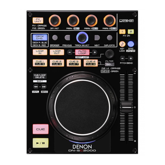
Page 6: Top Panel
1. TOP PANEL Proceeding : TOP PANEL (1) Remove the screws. Direction of photograph: B Direction of Direction of photograph: C photograph: D Direction of photograph: A... - Page 7 2. INNER PANEL Proceeding : TOP PANEL INNER PANEL → (1) Remove the knobs. KNOB (2) Remove the screws. Direction of photograph: B Direction of photograph: A...
- Page 8 3. CONTROL PCB ASS'Y Proceeding : TOP PANEL INNER PANEL CONTROL PCB ASS'Y → → (1) Remove the Nuts. (2) Remove the solder. Solder (3) Disconnect the connector wire, then remove the screws. CN102...
- Page 9 4. WHEEL ASS'Y Proceeding : TOP PANEL INNER PANEL WHEEL ASS'Y → → (1) Remove the screws. (2) Remove the screws. SENSOR PCB ASS'Y (3) Remove the SENSOR PCB ASS'Y. Note: Do not damage the WHEEL PLATE. WHEEL PLATE SENSOR PCB ASS'Y (4) Remove the E RING.
- Page 10 (3) PC Operation System will pop-up a new hard disc, named DN-SC2000. (4) Copy updated fi le (EX: DN-SC2000_v1.13.bin), and paste on “DN-SC2000” hard disc. (5) It will start updating. After updating successfully, DN-SC2000 will switch to Midi Controller automatically. (6) Firmware updating State CUE-1: Update Ready, CUE-2: Update Data(0%), CUE-3: Update Data(50%), CUE-4: Update Data(100%) FX UNIT: Update Success (* If it doesn’t light, it means “Updating Error”)
- Page 11 3. Version Display Press (SHIFT+NEXT+SYNC) at the same time, then connect SC2000 to PC to check the light buttons that represent F/W version. Press (Shift) to retrurn to Normal Mode. How to read the version number Firmware Version Leds (Ver X .YZ) X:The first digit numeric display.
-
Page 12: Test Mode
4. Test Mode (1) Press ing (SHIFT+PREVIOUS+SYNC) at the same time, then connect SC2000 to PC to start Test Moe. (2) When you enter the test mode LED lights. The combination of LED A and B in two ways for each combination, q →... - Page 13 ABOUT REPLACE THE MICROPROCESSOR WITH A NEW ONE When replaced of the U-PRO (Microprocessor) or the Flash ROM, confi rm contents of the following. After PWB Name Ref. No. Description Remark replaced MAIN IC101 MC9S08JM32CLH P/N : 941243004230P After replaced A : Mask ROM (With software).
-
Page 14: Trouble Shooting
TROUBLE SHOOTING FLOW CHART NO.1 (MAIN UNIT) The power cannot be turned on. Is the USB cable or the USB terminal of the PC side normal? Reconnect normally. Check JK101 and the periphery circuit, and replace it if defective. FLOW CHART No.2 (MAIN UNIT) +3.3V is not outputted. - Page 15 FLOW CHART No.4 (MAIN UNIT) The key operation is not Touch sence functioning. Are the contact point and the installation state of the JOG Wheel Replace the JOG wheel. Top panel normal? Is signal output from IC104 pin No.5? Replace IC104 Doesn't Touch : 0V / Touch : 5V Replace IC101.
-
Page 16: Block Diagram
BLOCK DIAGRAM PIC16F616 WHEEL (P.I.) PITCH VR ENCODER MC9S08JM32 74595 LED DRIVER USB JACK... - Page 17 PRINTED WIRING BOARDS CONTROL UNIT (COMPONENT SIDE) SENSOR UNIT (COMPONENT SIDE) 鉛フリー半田 半田付けには、鉛フリー半田 (Sn-Ag-Cu) を使用してください。 Lead-free Solder When soldering, use the Lead-free Solder (Sn-Ag-Cu).
- Page 18 CONTROL UNIT (FOIL SIDE) 鉛フリー半田 半田付けには、鉛フリー半田 (Sn-Ag-Cu) を使用してください。 Lead-free Solder When soldering, use the Lead-free Solder (Sn-Ag-Cu).
- Page 19 405-HDJ9800-1020 M301 WHEEL ENCODER VR101 CN102 W102 10KBX2 PITCH VBUS R111 LED25 LED1 VBUS R108 Q132 Q134 IC108 IC105 /URST C114ES C114ES CN101 74595 74595 IC102 C112 D152 C125 C122 R107 SMAJ-6.0A R160 R161 R162 R163 R164 R165 X101 5.6K 5.6K 5.6K 5.6K...
- Page 20 EXPLODED VIEW & POINTS OF GREASING Grease: Product name : RS Paste Maker : DAIZO corporation(Nichimoly) WARNING: Parts marked with this symbol have critical characteristics. Use ONLY replacement parts recommended by the manufacturer.
- Page 21 PARTS LIST OF EXPLODED VIEW zParts for which "nsp" is indicated on this table cannot be supplied. zP.W.B. ASS'Y for which "nsp" is indicated on this table cannot be supplied. When repairing the P.W.B. ASS'Y, check the board parts table and order replacement parts. zPart indicated with the mark "...
-
Page 22: Packing View
PACKING VIEW PARTS LIST OF PACKING & ACCESSORIES zParts for which "nsp" is indicated on this table cannot be supplied. zPart indicated with the mark " ★ " is not illustrated in the exploded view. zThe parts listed below are for maintenance only, might differ from the parts used in the unit in appearances or dimensions. Note: The symbols in the column "Remarks"... - Page 23 SEMICONDUCTORS Only major semiconductors are shown, general semiconductors etc. are omitted to list. The semiconductor which described a detailed drawing in a schematic diagram are omitted to list. 1. IC's MC9S08JM32 (IC101) PTC4 PTD2/KBIP2/ACMPO IRQ/TPMCLK SSAD RESET REFL PTF0/TPM1CH2 REFH PTF1/TPM1CH3 DDAD PTF2/TPM1CH4...
- Page 24 MC9S08JM32 Block Diagram USBDP USBDN ON-CHIP ICE AND HCS08 CORE DEBUG MODULE (DBG) PTA5– PTA0 USB SIE FULL SPEED BKGD/MS PTB7/ADP7 PTB6/ADP6 USB ENDPOINT TRANSCEIVER PTB5/KBIP5/ADP5 PTB4/KBIP4/ADP4 PTB3/SS2/ADP3 SPSCK2 8-/16-BIT SERIAL PERIPHERAL PTB2/SPSCK2/ADP2 RESET HCS08 SYSTEM CONTROL MOSI2 INTERFACE MODULE (SPI2) PTB1/MOSI2/ADP1 MISO2 PTB0/MISO2/ADP0...
- Page 25 MC9S08JM32 Device Pin Assignment Name Symbol Function PTC4 PTC4 Port C I/O IRQ/TPMCLK External Interrupt Pin RESET RESET Development system can directly reset the MCU system PTF0/TPM1CH2 PTF0 Port F I/O PTF1/TPM1CH3 PTF1 Port F I/O PTF2/TPM1CH4 PTF2 Port F I/O PTF3/TPM1CH5 PTF3 Port F I/O...
- Page 26 Name Symbol Function PTD7 PTD7 Port D I/O PTG2/KBIP6 PTG2 Port G I/O PTG3/KBIP7 PTG3 Port G I/O BKGD/MS BKGD Background/Mode Select PTG4/XTAL XTAL External Oscillator PTG5/EXTAL EXTAL External Oscillator VSSOSC VSSOSC Low-Power Oscillator PTC0/SCL PTC0 Port C I/O PTC1/SDA PTC1 Port C I/O PTC2...
- Page 27 PIC16F616 (IC104) RA5/T1CKI/OSC1/CLKIN RA0/AN0/C1IN+/ICSPDAT RA4/AN3/T1G/OSC2/CLKOUT RA1/AN1/C12IN0-/V /ICSPCLK RA3/MCLR/V RA2/AN2/T0CKI/INT/C1OUT RC5/CCP1/P1A RC0/AN4/C2IN+ RC4/C2OUT/P1B RC1/AN5/C12IN1- RC3/AN7/C12IN3-/P1C RC2/AN6/C12IN2-/P1D PIC16F616 Poin Summary Analog Comparators Timer Interrupts Pull-ups Basic C1IN+ — — ICSPDAT AN1/V C12IN0- — — ICSPCLK C1OUT T0CKI — INT/IOC — — — —...
- Page 28 PIC16F616 Block Diagram Configuration PORTA Data Bus Program Counter Flash 2K X 14 Program Memory 8-Level Stack 128 Bytes File (13-Bit) Registers Program RAM Addr Addr MUX Instruction Reg PORTC Indirect Direct Addr Addr FSR Reg STATUS Reg Power-up Timer Oscillator Instruction Start-up Timer...
- Page 29 PARTS LIST OF P.W.B. UNIT zParts for which "nsp" is indicated on this table cannot be supplied. zThe parts listed below are for maintenance only, might differ from the parts used in the unit in appearances or dimensions. Note: The symbols in the column "Remarks" indicate the following destinations. E3 : U.S.A.
- Page 30 Ref. No. Part No. Part Name Remarks Q'ty D184A LED HOLDER(LED3-1A-B,H=1.5mm,BLACK) 504-HDJ2000-097 D184B LED HOLDER(LED3-1A-B,H=1.5mm,BLACK) 504-HDJ2000-097 D170A LED HOLDER(LED3-1A-B,H=1.5mm,BLACK) 504-HDJ2000-097 D170B LED HOLDER(LED3-1A-B,H=1.5mm,BLACK) 504-HDJ2000-097 D186A LED HOLDER(LED3-1A-B,H=1.5mm,BLACK) 504-HDJ2000-097 D186B LED HOLDER(LED3-1A-B,H=1.5mm,BLACK) 504-HDJ2000-097 D166A LED HOLDER(LED3-1A-B,H=1.5mm,BLACK) 504-HDJ2000-097 D166B LED HOLDER(LED3-1A-B,H=1.5mm,BLACK) 504-HDJ2000-097 D168A LED HOLDER(LED3-1A-B,H=1.5mm,BLACK) 504-HDJ2000-097...
- Page 31 Ref. No. Part No. Part Name Remarks Q'ty D159A 941263002620S CHIP LED(JA-3020YG,3'2,YELLOW/GREEN) 410-MIX101-374 D159B 941263002620S CHIP LED(JA-3020YG,3'2,YELLOW/GREEN) 410-MIX101-374 D183A 941263002620S CHIP LED(JA-3020YG,3'2,YELLOW/GREEN) 410-MIX101-374 D183B 941263002620S CHIP LED(JA-3020YG,3'2,YELLOW/GREEN) 410-MIX101-374 D179A 941263002620S CHIP LED(JA-3020YG,3'2,YELLOW/GREEN) 410-MIX101-374 D179B 941263002620S CHIP LED(JA-3020YG,3'2,YELLOW/GREEN) 410-MIX101-374 D176A 941263002620S CHIP LED(JA-3020YG,3'2,YELLOW/GREEN) 410-MIX101-374 D176B...
- Page 32 Ref. No. Part No. Part Name Remarks Q'ty R126A CHIP RESISTOR(110OHM,J,1/10W,TP 0603,50V) 412-11-1255 R126B CHIP RESISTOR(110OHM,J,1/10W,TP 0603,50V) 412-11-1255 R131A CHIP RESISTOR(110OHM,J,1/10W,TP 0603,50V) 412-11-1255 R131B CHIP RESISTOR(110OHM,J,1/10W,TP 0603,50V) 412-11-1255 R132A CHIP RESISTOR(110OHM,J,1/10W,TP 0603,50V) 412-11-1255 R132B CHIP RESISTOR(110OHM,J,1/10W,TP 0603,50V) 412-11-1255 R138A CHIP RESISTOR(110OHM,J,1/10W,TP 0603,50V) 412-11-1255 R138B CHIP RESISTOR(110OHM,J,1/10W,TP 0603,50V)
- Page 33 Ref. No. Part No. Part Name Remarks Q'ty C106 CHIP CAPACITOR(0.47uF/50V Y5V/0603 SMD) 413-CDVD2001-751 C107-110 CHIP CAPACITOR(0.1uF/50V,M,0603 TYPE,Y5V) 413-DCM280-890 ELEC. CAPACITOR C111 00D9587054907 413-HMA2200-5017 (100uF/10V,M,105 ºC ,TAPING 5*7,MINI) C112,113 CHIP CAPACITOR(33pF/50V,J,0603 TYPE,NPO) 413-007USB-783 ELEC. CAPACITOR C114 00D9587030701 413-DV300-5156 (2.2uF/50V,M,105 ºC ,TAPING 4*7,MINI C115,116 CHIP CAPACITOR(3300pF/50V,K,0603 TYPE,X7R) 413-DCM280-770...
Need help?
Do you have a question about the DN-SC2000 and is the answer not in the manual?
Questions and answers