Table of Contents
Advertisement
Quick Links
Ver. 2
Please refer to the
MODIFICATION NOTICE.
SERVICE MANUAL
MODEL
JP
E3
E2
EK
E2A E2C E1K EUT
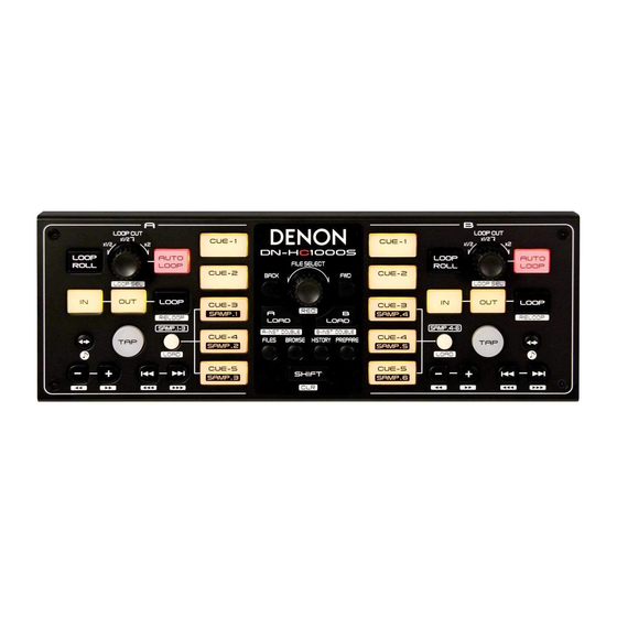
DN-HC1000S
USB MIDI CONTROLLER
For purposes of improvement, specifications and design are subject to change without notice.
●
Please use this service manual with referring to the operating instructions without fail.
●
Some illustrations using in this service manual are slightly different from the actual set.
●
S0013-1V02DM/DG0911
Copyright 2009 D&M Holdings Inc. All rights reserved.
WARNING: Violators will be prosecuted to the maximum extent possible.
Advertisement
Table of Contents

Subscribe to Our Youtube Channel
Summary of Contents for Denon DN-HC1000S
- Page 1 MODIFICATION NOTICE. SERVICE MANUAL MODEL E2A E2C E1K EUT DN-HC1000S USB MIDI CONTROLLER For purposes of improvement, specifications and design are subject to change without notice. ● Please use this service manual with referring to the operating instructions without fail.
-
Page 2: Safety Precautions
SAFETY PRECAUTIONS The following check should be performed for the continued protection of the customer and service technician. LEAKAGE CURRENT CHECK Before returning the unit to the customer, make sure you make either (1) a leakage current check or (2) a line to chassis resistance check. - Page 3 DIMENSION 88 mm...
-
Page 4: Firmware Update
Use the procedure described below to update the firmware to a newer version. (1) Press the BACK and FWD button at the same time, then connect DN-HC1000S to PC. (2) DN-HC1000S will enter updating mode. CUE-1(A, B) will light to indicate "Update Ready."... -
Page 5: Troubleshooting
TROUBLE SHOOTING FLOW CHART NO.1 (MAIN UNIT) The power cannot be turned on. Is normal state restored when once unplugged USB cord is plugged Is the USB cable or the USB terminal of the PC again? side normal? Check JK101 and the periphery circuit, and replace it if defective. FLOW CHART No.2 (MAIN UNIT) +3.3V is not outputted. - Page 6 SEMICONDUCTORS Only major semiconductors are shown, general semiconductors etc. are omitted to list. The semiconductor which described a detailed drawing in a schematic diagram are omitted to list. 1. IC’s MC9S08JM32 (IC101) PTC4 PTD2/KBIP2/ACMPO IRQ/TPMCLK SSAD RESET REFL PTF0/TPM1CH2 REFH PTF1/TPM1CH3 DDAD PTF2/TPM1CH4...
- Page 7 MC9S08JM32 Block Diagram USBDP USBDN ON-CHIP ICE AND HCS08 CORE DEBUG MODULE (DBG) PTA5– PTA0 USB SIE FULL SPEED BKGD/MS PTB7/ADP7 PTB6/ADP6 USB ENDPOINT TRANSCEIVER PTB5/KBIP5/ADP5 PTB4/KBIP4/ADP4 PTB3/SS2/ADP3 SPSCK2 8-/16-BIT SERIAL PERIPHERAL PTB2/SPSCK2/ADP2 RESET HCS08 SYSTEM CONTROL MOSI2 INTERFACE MODULE (SPI2) PTB1/MOSI2/ADP1 MISO2 PTB0/MISO2/ADP0...
- Page 8 74AHC595DR (IC102, 103, 104) handbook, halfpage handbook, halfpage SRG8 SH CP 8-STAGE SHIFT REGISTER Q 7 ' ST CP 8-BIT STORAGE REGISTER 3-STATE OUTPUTS Q 0 Q 1 Q 2 Q 3 Q 4 Q 5 Q 6 Q 7 15 1 MNA554 MNA553...
-
Page 9: Block Diagram
BLOCK DIAGRAM ENCODER MC9S08JM32 74595 LED DRIVER USB JACK... -
Page 10: Printed Wiring Board
PRINTED WIRING BOARD CONTROL PWB UNIT COMPONENT SIDE FOIL SIDE... - Page 11 NOTE FOR PARTS LIST Parts for which "nsp" is indicated on this table cannot be supplied. When ordering of part, clearly indicate "1" and "I" (i) to avoid mis-supplying. Ordering part without stating its part number can not be supplied. Part indicated with the mark "★"...
-
Page 12: Parts List Of P.w.b. Unit
PARTS LIST OF P.W.B. UNIT * Parts for which "nsp" is indicated on this table cannot be supplied. * The parts listed below are for maintenance only, might differ from the parts used in the unit in appearances or dimensions. CONTROL PWB ASS'Y Ref. - Page 13 Ref. No. Part No. Part Name Remarks Q'ty New R127B,R128B CHIP RESISTOR(150 OHM,1/10W,J,TP ,50V) 412-CD900-795 R129 CHIP RESISTOR(10K OHM,1/10W,J,TP ,50V) 412-CDVD2001-534 R130-R143 CHIP RESISTOR(100 OHM,1/10W,J,TP,50V) 412-CDVD2001-530 CAPASITORS GROUP C101-C103 CHIP CAPACITOR(0.1uF/50V,Z) 413-DCM280-773 C104 941134000520S E.C.(4.7uF/25V,MINI) 413-SMX701-712 C105 CHIP CAPACITOR(0.47uF/16V,Z) 413-U101-928 C106 CHIP CAPACITOR(0.1uF/50V,Z) 413-DCM280-773...
-
Page 14: Exploded View
EXPLODED VIEW WARNING: Parts marked with this symbol have critical characteristics. Use ONLY replacement parts recommended by the manufacturer. -
Page 15: Parts List Of Exploded View
PARTS LIST OF EXPLODED VIEW * Parts for which "nsp" is indicated on this table cannot be supplied. * P.W.B. ASS'Y for which "nsp" is indicated on this table cannot be supplied. When repairing the P.W.B. ASS'Y, check the board parts table and order replacement parts. *... -
Page 16: Packing View
PACKING VIEW PARTS LIST OF PACKING & ACCESSORIES * Parts for which "nsp" is indicated on this table cannot be supplied. * The parts listed below are for maintenance only, might differ from the parts used in the unit in appearances or dimensions. Ref. - Page 17 ---MEMO---...
-
Page 18: Note For Schematic Diagram
NOTE FOR SCHEMATIC DIAGRAM WARNING: Parts marked with this symbol z have critical characteristics. Use ONLY replacement parts recommended by the manufacturer. CAUTION: Before returning the unit to the customer, make sure you make either (1) a leakage current check or (2) a line to chassis resistance check. - Page 19 Q112 Q113 Q114 Q115 Q116 Q117 Q118 D110 D111 C114ES C114ES C114ES C114ES C114ES C114ES C114ES C114ES EDZC6.8B EDZC6.8B CHASSIS D129 D130 D131 D132 D133 D134 1SS35 5 1SS355 1SS355 1SS355 1SS35 5 1SS355 SCHEMATIC DIAGRAMS (1/1) CONTROL UNIT DN-HC1000S...


Need help?
Do you have a question about the DN-HC1000S and is the answer not in the manual?
Questions and answers