
Related Manuals for Volkswagen V10-TDI


Summary of Contents for Volkswagen V10-TDI
- Page 1 The Touareg V10-TDI Engine Design and Function Self-Study Program Course Number 89N303...
- Page 2 Volkswagen of America, Inc., its affiliated companies and its licensors. All rights are reserved to make changes at any time without notice.
- Page 3 Contents Introduction ......................1 The V10-TDI, Specifications, Power/Torque Diagram Engine Mechanics..................... 4 Cylinder Block,Endbracket, Cylinder Head, Connecting Bolt Principal, Crankshaft, Crank Pin Offset, Pistons and Connecting Rods, Balancing, Auxilary Drive and Components Oil Circulation, Coolant Circulation, Fuel System, Exhaust System, Overview of Engine Management Service ........................
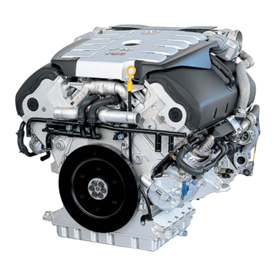
- Page 5 A milestone... ” With the V10-TDI engine, Volkswagen once again sets new standards in diesel technology. Due to a multitude of innovative techniques, the highest demands in terms of performance, torque and emissions of a diesel engine are fulfilled for the luxury vehicle class.
- Page 6 Introduction The V10-TDI Engine The V10-TDI engine is a newly developed diesel engine in which innovative lightweight construction and enormous power are united within compact dimensions. It has a 90 aluminum cylinder block with 5 cylinders in each bank of the block. The control and auxiliary drive are gear-driven.
- Page 7 Introduction Power Output / Torque 5.0 I - V10 - TDI - 308 hp (230 kW) @ 3750 RPM 533 lb ft (750 Nm) @ 2250 RPM 3,750 2,250 1000 2000 3000 4000 5000 = Power Output Engine (RPM) = Torque Engine Management Technical Features Engine Mechanics Technical Features •...
-
Page 8: Cylinder Block
Engine Mechanics Cylinder Block The cylinder block assembly consists of three components; an aluminum cylinder block, upper and a lower end brackets. The aluminum cylinder block provides a significant weight reduction for the 90° cylinder banks. The high tensile cast iron end brackets give the assembly a rigid platform. - Page 9 Engine Mechanics End Bracket The upper and lower end brackets are manufactured from high tensile cast iron. The upper and lower portions of the end brackets use a press fit; and 4 bolts per main journal to provide the crankshaft with a strong and rigid structure to contain the high combustion forces of the diesel engine.
-
Page 10: Cylinder Head
Engine Mechanics Cylinder Head The V10-TDI engine has two aluminium-alloy cylinder heads. The intake and exhaust ports are arranged according to the crossflow principle; that is, the intake and exhaust ports are located on opposite sides of the cylinder head. This arrangement provides good gas exchange and thus good cylinder filling. - Page 11 Engine Mechanics Crankshaft The crankshaft of the V10-TDI engine is made of tempered steel; forged from one piece. The auxiliary drive gear, engine speed sensor wheel, and bolted-on counterweights are located on Auxiliary Drive Gear the crankshaft. Bolted-on Counterweights 303_023...
-
Page 12: Pistons And Connecting Rods
Engine Mechanics Pistons and Connecting Rods Cooling Channel To keep the demands on the piston and connecting rods low at high combustion pressures, the piston pin bosses and the connecting rod boss have a trapezoidal shape. This distributes the combustion forces over a broader area. - Page 13 Engine Mechanics Balancing Vibration Damper To attain low vibration running of the engine, the The vibration damper reduces the rotational moments of inertia must be balanced. vibrations of the crankshaft. It is filled with a silicone oil. For this, 6 counterweights are attached to the crankshaft.
- Page 14 Engine Mechanics Auxiliary Drive and Components The auxiliary drive is located on the flywheel side. The camshafts and the auxiliary components are driven by the crankshaft by helical gears. The advantage of a gear drive over a toothed belt is that larger forces can be transferred while the size of the gears remains the same as the sprockets used for toothed belt.
- Page 15 Engine Mechanics Alternator Camshaft Drive Drive Module Crankshaft 303_016...
- Page 16 Engine Mechanics Camshaft Drive Gear, Alternator Drive Gear Cylinder Bank 1 Coolant Pump Drive Gear Compensation Gear Camshaft Drive Gear, Cylinder Bank 2 Crankshaft 303_003 Power Steering Pump and Bolted Connection with Bearing Air Conditioning System Tunnel Compressor Drive Gear Oil Pump/Balance Shaft Drive Gear...
- Page 17 Engine Mechanics Drive Module The drive module uses helical gears to drive the The gears have a helix angle of 15°; with two camshafts, coolant pump, alternator, power tooth mesh. The two tooth mesh provides a larger bearing surface that is stronger and steering pump and air conditioning compressor.
- Page 18 Engine Mechanics Shackle Joint The camshafts located in the cylinder head are driven by gears located in brackets called a shackle joint. The shackle joint is used to compensate for the end play of the gears and expansion of the aluminium cylinder heads and cylinder block throughout the entire operating temperature of the engine.
- Page 19 Engine Mechanics Balance Piston Preload on the shackle joint is achieved by a balance piston. The piston consists of a sleeve in which several spring washers are arranged behind one another, axially tensioned. Setting for “Warm Engine” Compensation Camshaft Gear Gear Shackles 303_017b...
- Page 20 Engine Mechanics Alternator The alternator is arranged in a space-saving manner in the V-space of the engine. It is driven by a Gates® drive via a gear drive on the transmission shaft. Due to the transmission shaft, the alternator speed increases by a factor of 3.6 compared to the engine speed.
- Page 21 Engine Mechanics Power Steering Pump/Air Conditioning System Compressor The power steering pump and the air conditioning system compressor are arranged in a row on the engine block. The power steering pump is driven directly by the gear drive. The air conditioning system compressor is driven by a Gates®...
- Page 22 Engine Mechanics Oil Circulation Bypass Valve Oil Cooler Oil Filter Oil Return Baffle Oil Return Baffle Oil Pressure Switch Oil Return Baffle Vacuum Pump Exhaust Turbocharger Piston with Cooling Channel Belt Drive Module Oil Supply Oil-Spraying Jets (Piston Cooling) Oil Pump Oil Separator 303_053 Return Oil...
- Page 23 Engine Mechanics Drive Module Oil Supply Main Channel in Cylinder Head Main Channel in Cylinder Head Cylinder Head Oil Line Oil Line Drive Module Oil Supply from Oil Channel Cylinder Block 303_054 Drive Module Oil Filter Module Oil Filter Module The oil filter module is located in a space-saving manner in the V-space of the engine.
- Page 24 Engine Mechanics Oil Pump The oil pump is located in the upper portion of return oil from the turbocharger oil returns to the the oil pan. It has oil pump rotors, that operate oil sump, ensuring that there is a sufficient according to the duo-centric principle.
- Page 25 Engine Mechanics Oil Pan The oil pan consists of two cast-aluminium The Touareg has a deep, lower part of the oil parts. pan, so it can hold a large amount of oil. In addition, the lower part of the oil pan of the The lines for the oil scavenge pumps are located Touareg has elastic flap traps.
- Page 26 Engine Mechanics Oil Scavenge System Two oil scavenge pumps are used to ensure an ample supply of oil in the sump in all driving conditions. The following examples describe the oil scavenge system in three different driving states. Pressurized Oil Channel Oil Return Auxiliary Oil Return...
- Page 27 Engine Mechanics Oil Scavenge System, Uphill Driving Pressurized Oil System Oil Return 303_020 During uphill driving or when accelerating, the oil flows into the rear area of the oil pan. The flap traps close, preventing the oil from flowing into the rear area of the oil pan. The oil scavenge pumps suction the oil out of the rear area of the oil pan, eliminating backpressure from the turbocharger and the auxiliary drive oil return.
- Page 28 Engine Mechanics Coolant Circulation System System Overview Engine Coolant Circulation Coolant Circulation for Alternator and 303_039 Fuel Cooling (Touareg Only) Warm Warm Cold Cold...
- Page 29 Coolant Circulation for Alternator and Fuel Recirculation Pump V55 Cooling The fuel cooling pump is an electrical circulation In the Touareg, the V10-TDI engine has a pump. If required, it is activated by the separate coolant circulation for the alternator Climatronic control unit, providing coolant and the fuel cooling.
- Page 30 Engine Mechanics Coolant Pump The coolant pump is located on the front of the engine block. It is driven by the belt drive module by a connection shaft. 303_047 Coolant Pump Drive Gear in Drive Module Connection Shaft Coolant Drain Plugs 303_075 Coolant Drain Plugs Two coolant drain plugs are located on the...
- Page 31 Engine Mechanics Thermostat for Map-Controlled Engine Cooling The thermostat for map-controlled engine cooling is located in the pipe union of the coolant controller housing. It switches between the large and the small coolant circulation systems. For this, it is activated by the ECM according to the requirements of the engine’s operating state.
- Page 32 Engine Mechanics Water Connection Coolant Connection The water connection is located in the V-space of the engine, above the coolant controller housing. It connects the coolant circulation of the two cylinder heads. The coolant is transported out of the cylinder heads through the two large connections to the coolant controller housing.
- Page 33 Engine Mechanics Removal and Installation To permit the coolant connection in the V-space of the engine to be removed and installed, the two large connections in the coolant connection housing can be pushed in/pulled apart. Coolant Connection - Assembly Position 303_105 Coolant Connection - Installed Position Coolant Connection Housing...
- Page 34 Engine Mechanics Fuel System The fuel is transported out of the fuel tank to the fuel filter unit by electrical fuel pumps. The mechanical fuel pumps suck the fuel out of the fuel filter unit and transport it at high pressure into the preliminary run of the fuel rails.
- Page 35 Engine Mechanics Fuel Manifold Fuel Cooler Connection Nozzle Fuel Return Pressure Relief Valve Vacuum Pump In the Touareg, the fuel is cooled by a fuel- to-coolant cooler. Fuel Pump 303_051...
- Page 36 Engine Mechanics Overall Schematic Diagram Fuel Return Pressure Relief Valve The Electrical Fuel Pumps work as preliminary Fuel transport pumps, pumping fuel to the fuel filter Temperature unit. Sensor The Check Valves prevent fuel in the fuel Pressure Control manifold and the preliminary run line from Valve flowing back into the fuel tank when the engine is at a standstill.
- Page 37 Engine Mechanics Pump - Injector Unit Fuel Manifold Coolant Fuel Cooler Electric Fuel Pump Fuel Manifold 303_088 Return Preliminary Run - Low pressure Preliminary Run - High pressure...
- Page 38 Engine Mechanics Fuel Filter Unit The fuel filter unit is located in a crash-safe position in the V-space of the engine. It contains two filter inserts and a sensor for the fuel contamination. The sensor for the fuel contamination is used to inform the driver if the water level in the filter unit is too high, using an indicator light in the dash panel insert.
- Page 39 Engine Mechanics Preheating Valve At low outside temperatures, diesel fuel tends to thicken. This can clog the fuel filter; as a result, operating the engine may no longer be possible due to a lack of fuel. Lid of Fuel Filter Warm Fuel Temperature Elastic Element Unit...
- Page 40 Engine Mechanics Pump-Injector Units Adjusting Screw The same type pump-injector units used in the 1.9l/74 kW TDI engine are also used in the V10-TDI engine. Stud They are characterized by: • A low-friction drive • An increased injection pressure in the...
- Page 41 Engine Mechanics Exhaust System The all-stainless steel exhaust system of the V10-TDI engine consists of one preliminary catalytic converter and one main catalytic converter per cylinder bank, as well as a preliminary silencer and a main silencer. All catalytic converters are oxidation catalytic converters.
- Page 42 Overview of Engine Management This section provides you with an overview of and functions of engine management can be the V10-TDI engine management system. A found in Self-Study Program 89P303, ” Touareg detailed description of the sensors, actuators Electronic Diesel Control EDC 16.
- Page 43 Engine Mechanics Altitude Sensor Valve for Pump Injector N240- N244 Fuel Pump (FP) Relay J17 Fuel Pump (FP) G6 Transfer Fuel Pump (FP) G23 Turbocharger 1 Servo-Motor V280 EGR Vacuum Regulator Solenoid Valve N18 Motor for Intake Flap V157 Turbocharger 2 Servo-Motor V281 MAP Controlled Engine Cooling Thermostat F265 Valve for Pump...
- Page 44 Service Service Designation Tool Usage T10191 To switch off the V10-TDI Frame engine 303_056 T10192 Removal and installation of the oil Oil Filter Key filter lid 303_057 T10193 To fasten the camshaft cylinder Camshaft Clamp bank 1 when setting the control times...
- Page 45 Service Service Designation Tool Usage T10195 To fasten the crankshaft when setting the Crankshaft Clamp control times 303_061 T10196 To install the PTFE crankshaft gasket on the flywheel side 303_061 T10197 For removal and installation of various Plug Cartridge SW6 add-on pieces in the V-space of the engine 303_062...
- Page 46 Service Service Designation Tool Usage T10199 Clamping the camshaft gears to Clamping Device remove and install the camshaft gears 303_064 T10200 For removal and installation of the Guide Pin belt drive module Figure not available at time of printing T10201 For removal and installation of the Clamping Device...
- Page 47 Service Service Designation Tool Usage T10126 To transport the V10-TDI engine Transport Shackle with workshop crane VAS 6100 303_108 T10207 To install the PTFE crankshaft gasket on Assembly Equipment the gearbox side 303_109 T10208 To install the PTFE crankshaft gasket on...
- Page 48 Notes _____________________________________________________________________________________ _____________________________________________________________________________________ _____________________________________________________________________________________ _____________________________________________________________________________________ _____________________________________________________________________________________ _____________________________________________________________________________________ _____________________________________________________________________________________ _____________________________________________________________________________________ _____________________________________________________________________________________ _____________________________________________________________________________________ _____________________________________________________________________________________ _____________________________________________________________________________________ _____________________________________________________________________________________ _____________________________________________________________________________________ _____________________________________________________________________________________ _____________________________________________________________________________________ _____________________________________________________________________________________ _____________________________________________________________________________________ _____________________________________________________________________________________ _____________________________________________________________________________________ _____________________________________________________________________________________ _____________________________________________________________________________________...
-
Page 49: Knowledge Assessment
Knowledge Assessment An on-line Knowledge Assessment (exam) is available for this Self-Study Program. The Knowledge Assessment may or may not be required for Certification. You can find this Knowledge Assessment at: www.vwwebsource.com From the vwwebsource.com Homepage, do the following: – Click on the Certification tab –... - Page 50 The Touareg V10-TDI Engine Volkswagen of America, Inc. 3800 Hamlin Road Auburn Hills, MI 48326 Printed in U.S.A. March 2003...
Need help?
Do you have a question about the V10-TDI and is the answer not in the manual?
Questions and answers