Table of Contents
Advertisement
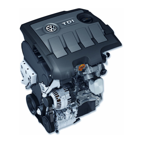
1.9-Liter TDI Engine
with Pump Injection
(Pumpe Düse)
Design and Function
Self-Study Program
Course Number 841303
Advertisement
Table of Contents

Related Manuals for Volkswagen 1.9-Liter TDI


Summary of Contents for Volkswagen 1.9-Liter TDI
- Page 1 1.9-Liter TDI Engine with Pump Injection (Pumpe Düse) Design and Function Self-Study Program Course Number 841303...
- Page 2 Volkswagen of America, Inc., its affiliated companies and its licensors. All rights are reserved to make changes at any time without notice.
-
Page 3: Table Of Contents
Introduction ................1 1.9-Liter TDI Engine with Pump Injection System Engine – Mechanics ..............2 Development of the 1.9-Liter TDI Engine with Pump Injection System, Technical Data – 1.9-Liter TDI Engine with Pump Injection System, Trapezoidal Piston and Connecting Rod, Toothed Belt Drive Fuel Supply ................ -
Page 5: Introduction
The 1.9-liter TDI engine with the new pump injection system meets the stringent demands for improved performance and cleaner emissions. -
Page 6: Engine – Mechanics
Engine – Mechanics Development of the 1.9-Liter TDI Engine with Pump Injection System The new 100 bhp (74 kW) 1.9-liter TDI engine with pump injection system was developed from the existing 109 bhp (81 kW) 1.9-liter TDI engine with a distributor injection pump and no intermediate shaft. - Page 7 Engine – Mechanics Technical Data – 1.9-Liter TDI Engine with Pump Injection System • Engine code lbs-ft Nm 221 300 • Type 184 250 Four-cylinder in-line engine with two valves per cylinder 148 200 • Displacement 115.7 cu in (1,896 cm 111 150 •...
- Page 8 Engine – Mechanics Trapezoidal Piston and Connecting Rod To accommodate the higher combustion pressures in the 1.9-liter TDI engine with pump injection system than are encountered in the base engine, the piston hub and the connecting rod eye are trapezoidal in shape.
- Page 9 Engine – Mechanics In comparison with the conventional Force Distribution in a Parallelogram-Shaped parallelogram-shaped link between the Piston and Connecting Rod piston and connecting rod, the trapezoidal connecting rod eye and piston hub have a Combustion Force larger contact surface area at the piston pin Contact Surface owing to their shape.
- Page 10 Engine – Mechanics Toothed Belt Drive High pump forces are required to generate high injection pressures of up to 27,846 psi (192,000 kPa / 1,920 bar). These forces subject the components of the toothed belt drive to high loads. To relieve the load on the toothed belt, several modifications have been made.
- Page 11 Deceleration Force Non-uniform tooth gap clearance On the 1.9-liter TDI engine with pump injection system, the crankshaft timing belt gear teeth have a larger gap clearance at these points to compensate for the change in belt tooth pitch and thus reduce toothed belt wear.
-
Page 12: Fuel Supply
Fuel Supply Fuel Supply System Overview A mechanical fuel pump sucks the fuel out The fuel that is not required for injection is of the fuel tank through the fuel filter and returned to the fuel tank via the return line pumps it along the supply line in the in the cylinder head, a fuel temperature cylinder head to the pump/injectors. - Page 13 Fuel Supply Pressure Limiting Valve Bypass – If there is air in the fuel system, Cylinder Head for example when the fuel tank is empty, the pressure limiting valve remains closed. The air is expelled from the system by the fuel flowing into the tank.
- Page 14 Fuel Supply Fuel Pump The fuel pump is located directly behind There is a fitting on the fuel the vacuum pump at the cylinder head. pump for connecting pressure It moves the fuel from the fuel tank to the gauge VAS 5187 to check the pump/injectors.
- Page 15 Fuel Supply The fuel pump is a blocking vane-cell pump. The fuel ducting system within the pump The blocking vanes are pressed against the is designed so that the rotor always pump rotor by spring pressure. This design remains wetted with fuel, even if the tank enables the fuel pump to deliver fuel even has been run dry.
- Page 16 Fuel Supply Function Chamber 4 Chamber 3 The fuel pump operates by taking fuel in as the pump chamber volume increases and pushing the fuel out under pressure as the chamber volume is reduced. The fuel is drawn into two chambers and pumped out from two chambers.
- Page 17 Fuel Supply Distributor Pipe A distributor pipe is integrated in the fuel supply line in the cylinder head. It distributes the fuel evenly to the pump/injectors at a uniform temperature. SSP209/040 Cylinder 1 Cylinder 2 Cylinder 3 Cylinder 4 Cylinder Head Annular Gap Cross Holes Distributor Pipe...
- Page 18 Fuel Supply Fuel Cooling System Pump for Fuel Cooler V166 is an electric recirculation pump. It circulates the coolant The high pressure generated by the pump/ in the fuel cooling circuit through the injectors heats up the unused fuel so much auxiliary water cooler and the fuel cooler.
-
Page 19: Pump Injection System
Pump Injection System Pump/Injectors A pump/injector is, as the name implies, a Just like a conventional system with a pressure-generating pump combined with a distributor injection pump and separate solenoid valve control unit (Valves for Pump/ injectors, the new pump injection Injectors, Cylinders 1 through 4, N240, system must: N241, N242, and N243) and an injector. - Page 20 Pump Injection System The pump/injectors are installed directly in the cylinder head. SSP209/086 They are attached to the cylinder head by individual clamping blocks. It is important to ensure that Clamping the pump/injectors are positioned Block correctly when they are installed. Refer to the Repair Manual for instructions.
- Page 21 Pump Injection System Design Roller-Type Rocker Arm Ball Pin Pump Piston Injection Cam Piston Spring Solenoid Valve Needle Pump/Injector High-Pressure Solenoid Valve Chamber O-Ring Fuel Return Line Retraction Piston Fuel Supply Line O-Ring Injector Spring Injector Needle O-Ring Damping Element Injector Needle Heat- Insulating...
- Page 22 Pump Injection System Drive Mechanism The camshaft has four additional cams for driving the pump/injectors. They activate the pump/injector pump pistons with roller-type rocker arms. Injection Cam (Hidden by Rocker Arm Roller) Valve Cam Roller-Type Rocker Arm SSP209/015...
- Page 23 Pump Injection System Roller-Type Rocker Arm The injection cam has a steep leading edge and a gradual slope to the trailing edge. As a result of the steep leading edge, the pump piston is pushed down at high velocity. A high injection pressure is attained quickly.
- Page 24 Pump Injection System Mixture Formation and Main injection phase Combustion Requirements The key requirement for the main injection Good mixture formation is a vital factor to phase is the formation of a good mixture. ensure efficient combustion. The aim is to burn the fuel completely if possible.
- Page 25 Pump Injection System Injection Cycle High-Pressure Chamber Fills The solenoid valve needle is in its resting position. During the filling phase, the pump piston moves upward under the force of the The path is open from the fuel supply line piston spring and thus increases the to the high-pressure chamber.
- Page 26 Pump Injection System Pre-Injection Phase Starts The solenoid valve needle is pressed into the valve seat and closes the path from The injection cam pushes the pump the high-pressure chamber to the fuel piston down via the roller-type rocker arm. supply line.
- Page 27 Pump Injection System Injector needle damping During the pre-injection phase, the stroke of the injector needle is dampened by a hydraulic cushion. As a result, it is possible to meter the injection quantity exactly. Injector Spring Chamber Function Injector Spring In the first third of the total stroke, the Injector injector needle is opened undamped.
- Page 28 Pump Injection System Pre-Injection Phase Ends This ends the pre-injection phase. The pre-injection phase ends immediately The downward movement of the retraction after the injector needle opens. piston pre-loads the injector spring to a greater extent. The rising pressure causes the retraction piston to move downward, thus increasing To re-open the injector needle during the the volume of the high-pressure chamber.
- Page 29 Pump Injection System Main Injection Phase Starts The injector needle is again lifted from its seat and the main injection quantity The pressure in the high-pressure is injected. chamber rises again shortly after the injector needle closes. The pressure rises to between 27,121 psi (187,000 kPa / 1,870 bar) and 27,846 psi The pump/injector solenoid valve (192,000 kPa / 1,920 bar) because more...
- Page 30 Pump Injection System Main Injection Phase Ends The injector needle closes and the injector spring presses the bypass piston into its The injection cycle ends when the Diesel starting position. Direct Fuel Injection Engine Control Module J248 stops activating the pump/injector This ends the main injection phase.
- Page 31 Pump Injection System Pump/Injector Fuel Return The fuel return line in the pump/injector has the following functions: • Cool the pump/injector by flushing fuel from the fuel supply line through the pump/injector ducts into the fuel return line. • Discharge leaking fuel at the pump piston.
-
Page 32: Engine Management
Engine Management 1.9-Liter TDI Engine EDC 16 System Overview Sensors Diesel Direct Mass Air Flow Sensor G70 Barometric Fuel Injection Pressure Engine Control Sensor F96 Module J248 Engine Speed Sensor G28 Camshaft Position Sensor G40 Throttle Position Sensor G79 Kick Down Switch F8... - Page 33 Engine Management Actuators Glow Plugs Q6 Glow Plug Relay J52 Valve for Pump/Injector, Cylinder 1 N240 Valve for Pump/Injector, Cylinder 2 N241 Valve for Pump/Injector, Cylinder 3 N242 Valve for Pump/Injector, Cylinder 4 N243 Glow Plug Indicator Light K29 EGR Vacuum Regulator Solenoid Valve N18 Wastegate Bypass Regulator Valve N75 Change-Over Valve for Intake Manifold Flap N239 Transmission...
- Page 34 Engine Management Sensors Camshaft Camshaft Position Camshaft Position Sensor G40 Sensor Wheel Sensor G40 The Camshaft Position Sensor G40 is a Hall-effect sensor. It is attached to the toothed-belt guard below the camshaft gear. It scans seven teeth on the camshaft sensor wheel attached to the camshaft gear.
- Page 35 Engine Management Cylinder recognition when starting the engine When starting the engine, the Diesel Direct Fuel Injection Engine Control Module J248 must determine which cylinder is in the compression stroke in order to activate the correct pump/injector valve. To achieve this, it evaluates the signal generated by the Camshaft Position Sensor G40, which scans the teeth of the camshaft sensor...
- Page 36 Engine Management Function Each time a tooth passes the Camshaft Position Sensor G40, a Hall-effect voltage is induced and transmitted to the Diesel Direct Fuel Injection Engine Control Module J248. Because the teeth are spaced at different distances apart, the induced voltage occurs at different time intervals.
- Page 37 Engine Management Engine Speed Sensor G28 The Engine Speed Sensor G28 is an inductive sensor. It is attached to the cylinder block. SSP209/056 Engine speed sensor wheel The Engine Speed Sensor G28 scans a 60-2-2 sensor wheel attached to the crankshaft.
- Page 38 Engine Management Quick-Start Function By interpreting the signals from these two sensors, the Diesel Direct Fuel Injection To allow the engine to be started quickly, Engine Control Module J248 determines the Diesel Direct Fuel Injection Engine the position of the crankshaft in relation to Control Module J248 evaluates the signals the camshaft and thus the positions of the generated by the Camshaft Position Sensor...
- Page 39 Engine Management Fuel Temperature Sensor G81 The Fuel Temperature Sensor G81 is located in the fuel return line between the fuel pump and the fuel cooler. It determines the current temperature of the fuel at that point. The Fuel Temperature Sensor G81 has a negative temperature coefficient.
- Page 40 Engine Management Mass Air Flow Sensor G70 The Mass Air Flow Sensor G70 with reverse flow recognition is located in the intake pipe. It determines the intake air mass. The opening and closing actions of the valve produce reverse flows in the induced air mass in the intake pipe.
- Page 41 Engine Management Engine Coolant Temperature Sensor G62 The Engine Coolant Temperature Sensor G62 is located at the coolant connection on the cylinder head. It sends information about the current coolant temperature to the Diesel Direct Fuel Injection Engine Control Module J248. Signal application The Diesel Direct Fuel Injection Engine Control Module J248 uses the coolant...
- Page 42 Engine Management Accelerator Pedal Sensors The accelerator pedal sensors are integrated into a single housing and connected to the pedal by mechanical linkage. • Throttle Position Sensor G79 • Kick Down Switch F8 • Closed Throttle Position Switch F60 Signal application The Diesel Direct Fuel Injection Engine Control Module J248 can recognize the position of the accelerator pedal from...
- Page 43 Engine Management Intake Manifold Sensors The intake manifold sensors are integrated into a single module and installed in the intake pipe. • Manifold Absolute Pressure Sensor G71 • Intake Air Temperature Sensor G72 Manifold Absolute Pressure Sensor G71 Signal application The Manifold Absolute Pressure Sensor G71 supplies a signal that is required to check the charge pressure (boost...
- Page 44 Engine Management Barometric Pressure Sensor F96 Barometric Pressure Sensor F96 The Barometric Pressure Sensor F96 is located inside the Diesel Direct Fuel Injection Engine Control Module J248. Signal application The Barometric Pressure Sensor F96 sends the current ambient air pressure to the Diesel Direct Fuel Injection Engine SSP209/061 Control Module J248.
- Page 45 Engine Management Brake Pedal Sensors The brake pedal sensors are integrated into a single module that is mounted on the brake pedal bracket. • Brake Light Switch F • Brake Pedal Switch F47 Signal application Both switches supply the Diesel Direct Fuel Injection Engine Control Module J248 with the “brake activated”...
- Page 46 Engine Management Additional Input Signals Cruise control switch The signal generated by the cruise control switch tells the Diesel Direct Fuel Injection Engine Control Module J248 that the cruise control system has been activated. Three-phase AC generator terminal DF The signal supplied by generator terminal DF indicates the load state of the three- phase AC generator to the Diesel Direct SSP209/083...
- Page 47 Engine Management Actuators Pump/Injector Solenoid Valves The 1.9-liter TDI engine with the new pump injection system uses four pump/injector solenoid valves: • Valve for Pump/Injector, Cylinder 1 N240 • Valve for Pump/Injector, Cylinder 2 N241 • Valve for Pump/Injector, Cylinder 3 N242 •...
- Page 48 Engine Management Effects of failure If a pump/injector solenoid valve fails, the engine will not run smoothly and performance will be reduced. The pump/injector solenoid valve has a dual safety function. If the valve stays open, pressure cannot build up in the pump/injector. If the valve stays closed, the high-pressure chamber of the pump/injector can no longer be filled.
- Page 49 Engine Management Pump/injector solenoid valve monitoring “Start of injection” is the point in time when the actuating The Diesel Direct Fuel Injection Engine current to the pump/injector Control Module J248 monitors the electrical solenoid valve is initiated. current that actuates the solenoid valves at the pump/injectors.
- Page 50 Engine Management The actual moment at which the pump/ injector solenoid valve closes (BIP) is used by the Diesel Direct Fuel Injection Engine Control Module J248 to calculate the point of actuation for the next injection period. If the actual BIP deviates from the mapped details stored in the Diesel Direct Fuel Injection Engine Control Module J248, it will correct the point of valve actuation (start of...
- Page 51 Engine Management Change-Over Valve for Intake Manifold Flap N239 The Change-Over Valve for Intake Manifold Flap N239 is located in the engine compartment, in the vicinity of the Mass Air Flow Sensor G70. It switches the vacuum for actuating the intake manifold flap in the intake pipe.
- Page 52 Engine Management Effects of failure If the Change-Over Valve for Intake Manifold Flap N239 fails, the intake manifold flap stays open. The tendency of the engine to shudder when switched off will increase. Electrical circuit J217 Transmission Control Module J317 J248 Diesel Direct Fuel Injection Engine Control Module N239 Change-Over Valve for Intake...
- Page 53 Engine Management Relay for Pump, Fuel Cooling J445 The Relay for Pump, Fuel Cooling J445 is located on the engine control module mounting bracket. It is activated by the Diesel Direct Fuel Injection Engine Control Module J248 at a fuel temperature of 158°F (70°C) and switches the working current for the Pump for Fuel Cooler V166.
- Page 54 Engine Management Wastegate Bypass Regulator Valve N75 The engine has a variable turbine geometry for optimally adapting the charge pressure to the actual driving conditions. To regulate the charge pressure, the vacuum in the vacuum unit for turbocharger vane adjustment is set depending on the pulse duty factor.
- Page 55 Engine Management EGR Vacuum Regulator Solenoid Valve N18 The EGR Vacuum Regulator Solenoid Valve N18 enables the exhaust gas recirculation system to mix a portion of the exhaust gases with the fresh air supplied to the engine. This lowers the combustion temperature and reduces the formation of oxides of nitrogen.
- Page 56 Engine Management Additional Output Signals Engine speed This signal provides information on engine speed for the tachometer in the instrument cluster. Cooling fan run-on The run-on period of the cooling fan is controlled according to a characteristic curve stored in the Diesel Direct Fuel Injection Engine Control Module J248.
-
Page 57: Glow Plug System
Glow Plug System Glow Plug System The glow plug system makes it easier Glow Period to start the engine at low outside The glow plugs are activated when the temperatures. It is activated by the ignition is switched on and outside Diesel Direct Fuel Injection Engine Control temperature is below 48°F (9°C). -
Page 58: Functional Diagram
Functional Diagram EDC 16 Functional Diagram for 1.9-Liter TDI Engine Additional Signals Components Brake Lights Cruise Control Switch Fuel Consumption Signal Brake Light Switch Kick Down Switch Engine Speed Signal Clutch Vacuum Vent Valve Switch Brake Pedal Switch Air Conditioner Compressor Cut-Off... - Page 59 Functional Diagram J 317 J445 A/ + J360 J359 N239 N75 N18 V166 J248 N240 N241 N242 N243 F60/F8 G79 SSP209/080...
- Page 60 Service Self-Diagnosis The following functions can be read out using the Vehicle Diagnosis, Test and Information System VAS 5051: 01 Interrogate control unit version 02 Interrogate fault memory 03 Actuator diagnosis 04 Basic adjustment 05 Erase fault memory 06 End of output 07 Encode control unit 08 Read measured value block SSP209/082...
- Page 61 Service Pump/Injector Adjustment After installing a pump/injector, the For a complete description of minimum clearance between the base of this adjustment procedure, the high-pressure chamber and the pump refer to the Repair Manual. piston must be adjusted at the pump/ injector adjusting screw.
- Page 62 Service Special Tools Marking Plate T 10008 Holds the hydraulic toothed belt tensioner in place when installing and removing the toothed belt. SSP209/090a Crankshaft Stop T 10050 Holds the crankshaft in place at the crankshaft gear when adjusting the port timing. SSP209/090b Camshaft Gear Counter-Holder T 10051...
- Page 63 Service Socket Insert T 10054 Pump/injector clamping block fastener installation. SSP209/090f Pump/Injector Puller T 10055 Pump/injector removal from the cylinder head. SSP209/090g Pump/Injector O-Ring Assembly Sleeves T 10056 O-ring installation on the pump/injectors. SSP209/090h Shackle T 10059 This shackle is used to remove and install the engine in the Passat.
- Page 64 Notes...
-
Page 65: Knowledge Assessment
Knowledge Assessment An on-line Knowledge Assessment (exam) is available for this Self-Study Program. The Knowledge Assessment may or may not be required for Certification. You can find this Knowledge Assessment at: www.vwwebsource.com From the vwwebsource.com Homepage, do the following: – Click on the Certification tab –... - Page 67 Volkswagen of America, Inc. 3800 Hamlin Road Auburn Hills, MI 48326 Printed in U.S.A. October 2003...
Need help?
Do you have a question about the 1.9-Liter TDI and is the answer not in the manual?
Questions and answers