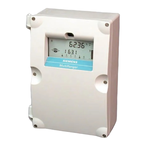
Siemens MultiRanger 200 Application Manual
Flow application configuration, configuring to measure open channel flow
Hide thumbs
Also See for MultiRanger 200:
- Quick start manual (128 pages) ,
- Quick start manual (118 pages)
Advertisement
Quick Links
Flow Application Configuration
Configuring the MultiRanger 200 to measure open channel flow
Objective:
Specific parameter setting to configure the following primary measurement devices:
MultiRanger 200, transducer, IR Hand Held Programmer or Dolphin Plus software, and primary
Equipment:
measurement device.
While every effort was made to verify the following information, no warranty of accuracy or usability is expressed or implied.
Overview:
This application guide is an addition to the instruction manual. Please review manual to ensure you are familiar with configuring
the MultiRanger 200 using the IR Hand Held Programmer or the Dolphin Plus software tool.
Setting up the Common Parameters
These parameters are configured for all the open channel flow measuring applications supported by the MultiRanger 200.
Parameter
Parameter Index*
P001
G
P002
G
P003
G
P004
G
P005
G
P006
G
P007
G
P801
G
*
G means 'global.' If f you have dual channel unit then the index is either 1 or 2 . For both, select 00.
**
Here we have chosen one value. Other choices can be selected from the manual as needed.
Siemens Milltronics Process Instruments Inc.
1954 Technology Drive, P.O. Box 4225, Peterborough, ON Canada K9J 7B1
Tel: (705) 745-2431 Fax: (705) 741-0466
Email: techpubs@siemens-milltronics.com
•
exponential devices
•
Palmer-Bowlus Flume
•
H-Flume
•
Universal Linear Flow Calculation
Value
6
1
2
102 (example)
1 (example)
Empty Distance
Span of Head
measurement
Range Extension
www.siemens-milltronics.com
APPLICATION GUIDE
•
Universal Curved Flow Calculation
•
BS 3680/ISO 4359 Rectangular Flume
•
BS 3680/ISO 1438/1 Thin Plate V-Notch Weir
Parameter and Value Definition **
Selects Open Channel Flow measurement.
Sets measured material to liquid.
Sets maximum processing speed, or speed of response, to
medium.
Selects transducer (e.g. 102 = XPS 10) connected to MultiRanger
200.
Sets units for head measurement (e.g 1 = meters).
Sets the distance from zero point of measurement (many times
bottom of the weir or channel) to the sensor surface. Head is
measured with reference to this zero point
Sets the range of head measurement. Often equal to the maximum
head.
Permits the liquid level to go below the zero point to the amount set
here without indicating an LOE condition (pre-set is 20% of span).
AG040305
Advertisement

Summary of Contents for Siemens MultiRanger 200
- Page 1 MultiRanger 200 using the IR Hand Held Programmer or the Dolphin Plus software tool. Setting up the Common Parameters These parameters are configured for all the open channel flow measuring applications supported by the MultiRanger 200. Parameter Parameter Index*...
-
Page 2: Application Guide
The MultiRanger 200 supports the following primary measuring devices to calculate the flow rate based on either the Absolute method or Ratiometric method. The design standards of these devices are programmed in the MultiRanger 200, and it applies the correct standard formula to calculate the flow. - Page 3 Q = Q (H/H Value Table Flow rate calculated and displayed by MultiRanger 200. The units will not be displayed and user must know the measurement units (liters/sec. or gallons/min. etc.). Maximum flow (at maximum head H ) as configured in P604. Its value is user provided, and is shown as a standalone number with no units indicated.
- Page 4 )/f(H / D) Value Table Flow rate calculated and displayed by MultiRanger 200. The units will not be displayed and user must know the measurement units used (liters/sec. or gallons/min. etc.). Maximum flow (at maximum head H ) as configured in P604. Its value is user provided, and is shown as a standalone number with no units indicated.
- Page 5 )/f(H / D) Value Table Flow rate calculated and displayed by MultiRanger 200. The units will not be displayed and user must know the measurement units used (liters/sec. or gallons/min. etc.). Maximum flow (at maximum head H ) as configured in P604. Its value is user provided, and is shown as a standalone number with no units indicated.
- Page 6 P610 (Head breakpoints) and P611 (Flow breakpoints) can be defined. With maximum head value defined in P603 and corresponding maximum flow value defined in P604, a total of 33 discrete points are available to the MultiRanger 200 for flow rate calculation.
- Page 7 Q = Q x f(H)/f(H Value Table Flow rate calculated and displayed by MultiRanger 200. The units will not be displayed and user must know the measurement units used (liters/sec. or gallons/min. etc.). Maximum flow (at maximum head H ) as configured in P604. Its value is user provided, and is shown as a standalone number with no units indicated.
- Page 8 Throat length Section 6.1 BS-3680/ISO 4359 Rectangular Flume Flow Calculation Equation The MultiRanger 200 calculates flow rate (Q) based on the Absolute calculation method confirming to BS 3680 Part 4C standard for Rectangular flumes and uses the following equation: Q = (2/3)
- Page 9 To calculate the flow rate this method requires only the angle of the weir notch ( ) in degrees. Section 7.1 BS-3680/ISO 1438 Thin plate V Notch Flow Calculation The MultiRanger 200 calculates flow rate (Q) based on Absolute calculation method confirming to BS 3680 Part 4A standard for thin plate weirs using the following equation:...
- Page 10 Both Primary devices BS 3680 / ISO 4359 Rectangular Flume and the BS 3680 / ISO 1438/1 Thin Plate V notch weir can also be configured for Ratiometric calculation in case the flow rate units are not supported in P608. MultiRanger 200 and Flow Configuration AG040303...


Need help?
Do you have a question about the MultiRanger 200 and is the answer not in the manual?
Questions and answers