Table of Contents
Advertisement
Quick Links
Advertisement
Table of Contents

Related Manuals for Microsemi LX7302


Summary of Contents for Microsemi LX7302
- Page 1 LX7302 User Guide LX7302 Evaluation Board Preliminary November 2018...
-
Page 2: Table Of Contents
3 Evaluation Board Operation ......................3 4 PCB Layout Guidelines ........................4 5 Test Considerations ........................10 6 Evaluation Board Test Data ......................11 7 Evaluation Board Schematic ......................18 8 Bill of Materials ..........................19 Microsemi Proprietary and Confidential. LX7302 User Guide Revision 2.0... -
Page 3: Revision History
Revision 2.0 was published in November 2018. In Revision 1.1, Table 3 (see page 19) was updated. Revision 1.0 Revision 1.0 was published in 2012. It was the first publication of this document. Microsemi Proprietary and Confidential. LX7302 User Guide Revision 2.0... -
Page 4: Product Description
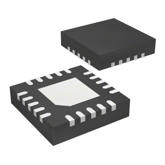
Programmable VID control or external reference Over-current protection Over- and under-voltage protection Power saving mode Power OK indicator The LX7302 device is housed in a 3 mm × 3 mm 20-pin plastic QFN package. Microsemi Proprietary and Confidential. LX7302 User Guide Revision 2.0... -
Page 5: Evaluation Board Operation
Enable input. Enable control for the LX7302. A voltage greater than 2.5 V on this pin will disable the LX7302. External reference input. A 0 V to 2.2 V input to this pin controls the output voltage when in external reference mode. -
Page 6: Pcb Layout Guidelines
L1 as possible. The signal developed across C1 should be routed back to the LX7302 IC using a differential pair. The connections from the point of load to the LX7302’s FB and AGND pins should also be routed as a differential pair. - Page 7 LX7302 Evaluation Board Figure 1 • PCB Critical Traces Figure 2 • Silkscreen Top Microsemi Proprietary and Confidential. LX7302 User Guide Revision 2.0...
- Page 8 LX7302 Evaluation Board Figure 3 • Top Layer Microsemi Proprietary and Confidential. LX7302 User Guide Revision 2.0...
- Page 9 LX7302 Evaluation Board Figure 4 • Ground Layer Microsemi Proprietary and Confidential. LX7302 User Guide Revision 2.0...
- Page 10 LX7302 Evaluation Board Figure 5 • Power Layer Microsemi Proprietary and Confidential. LX7302 User Guide Revision 2.0...
- Page 11 LX7302 Evaluation Board Figure 6 • Bottom Layer Microsemi Proprietary and Confidential. LX7302 User Guide Revision 2.0...
-
Page 12: Test Considerations
The following is a guideline for testing the LX7302 IC: The LX7302 evaluation board will provide up to 30 A of continuous load current. The board comes with through-hole pads to accommodate 16 AWG wire for high-current testing. It is recommended to use these pads when operating at load currents in excess of 5 A. -
Page 13: Evaluation Board Test Data
LX7302 Evaluation Board Evaluation Board Test Data This section features the evaluation board test data graphs for the LX7302. Figure 7 • Load Regulation Figure 8 • Line Regulation Microsemi Proprietary and Confidential. LX7302 User Guide Revision 2.0... - Page 14 LX7302 Evaluation Board Figure 9 • Efficiency vs. Output Current Figure 10 • Soft Start, 5 A Load Microsemi Proprietary and Confidential. LX7302 User Guide Revision 2.0...
- Page 15 LX7302 Evaluation Board Figure 11 • Start-Up Profile, 5 A Load Microsemi Proprietary and Confidential. LX7302 User Guide Revision 2.0...
- Page 16 LX7302 Evaluation Board Figure 12 • PSM Start-Up into 1 A Load Microsemi Proprietary and Confidential. LX7302 User Guide Revision 2.0...
- Page 17 LX7302 Evaluation Board Figure 13 • Soft Shutdown No Load Microsemi Proprietary and Confidential. LX7302 User Guide Revision 2.0...
- Page 18 LX7302 Evaluation Board Figure 14 • VID00 to VID11 Change; 0.2 Ω Load Microsemi Proprietary and Confidential. LX7302 User Guide Revision 2.0...
- Page 19 LX7302 Evaluation Board Figure 15 • VID11 to VID00 Change; 0.2 Ω Load Microsemi Proprietary and Confidential. LX7302 User Guide Revision 2.0...
-
Page 20: Evaluation Board Schematic
LX7302 Evaluation Board Evaluation Board Schematic The section shows the schematic of the LX7302 evaluation board. Figure 16 • Evaluation Board Schematic Microsemi Proprietary and Confidential. LX7302 User Guide Revision 2.0... -
Page 21: Bill Of Materials
LX7302 Evaluation Board Bill of Materials The following table lists the bill of materials for the LX7302 device. Table 3 • Bill of Materials Item Quantity Part Description Manufacturer Manufacturer Part Number Reference Number Capacitor, ceramic, 0.47 µF, 10 V, 10%,... - Page 22 TP7, TP8, TP9, TP14, TP15, TP16, TP17, TP18, TP19, TP20, TP21 IC, LX7302 step-down DC-DC Microsemi LX7302 controller, 3 mm × 3 mm 20-pin QFN Printed circuit board Microsemi SGE3247 X3 Microsemi Proprietary and Confidential. LX7302 User Guide Revision 2.0...
- Page 23 Microsemi. It is the Buyer's responsibility to independently determine suitability of any products and to test and verify the same. The information provided by Microsemi hereunder is provided "as is, where is" and with all faults, and the entire risk associated with such information is entirely with the Buyer.
Need help?
Do you have a question about the LX7302 and is the answer not in the manual?
Questions and answers