Table of Contents
Advertisement
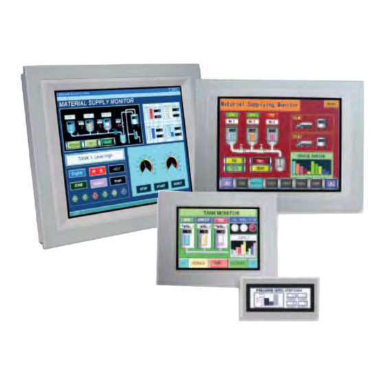
OI Touchscreen
Basic Tutorial
This Tutorial describes the basic procedures for
programming a screen using WindO/I-NV2 software.
It is intended for users who are trying IDEC OI
Touchscreens for the first time and for those who
wish to master the fundamentals of WindO/I-NV2
software.
IDEC
Touchscreen Family
www.IDEC.com/usa
Chapter 1
Introduction
Chapter 2
Installation
Chapter 3
Screen Creation
Chapter 4
Download
Chapter 5
Operation Check
Chapter 6
Appendix
Advertisement
Table of Contents

Subscribe to Our Youtube Channel
Summary of Contents for IDEC HG4F
- Page 1 Installation This Tutorial describes the basic procedures for programming a screen using WindO/I-NV2 software. It is intended for users who are trying IDEC OI Touchscreens for the first time and for those who Chapter 3 wish to master the fundamentals of WindO/I-NV2 Screen Creation software.
-
Page 2: Table Of Contents
Start Debug Mode ............38 Verify Operation with the Screen Monitor ....39 End Debugging Mode ..........41 Chapter 6 - Appendix 1. Tools and Functions ............42 Shortcut Keys ............42 Object List ..............42 Project List ..............43 System Requirements ..........44 Operator Interface Models ........44 www.IDEC.com/usa... -
Page 3: Chapter 1 Introduction
Chapter 1 Introduction 1 Operator Interface Features Features Design Tool Compatible With All IDEC OI Touchscreens - Users can easily create screens and setup operations by using the design tool, WindO/I-NV2 software. Supports Multiple Languages - The Operator Interface supports multiple languages, such as Japanese, Chi- nese (simplified and traditional Chinese characters), Korean, and European lan- guages. -
Page 4: Operator Interface Advantages
- Applicable to multiple items (Easy to add and modify components) - Multifunction, flexibility in expansion Operate screens by touching Parts can be directly with a finger. placed anywhere. Easily switch between displayed screens. Enter data with a numeric keypad. www.IDEC.com/software... -
Page 5: Windo/I-Nv2 Overview
*2: To supply power to the Operator Interface, a 24 V DC power supply is required. If the OI Touchscreen will be configured to communicate with a host (ie. PLC), then you will also need the following: (5) Programmable Controller (PLC) Example: MicroSmart (6) Communication Cable (between the MicroSmart & OI) Example: FC4A-KC2CA www.IDEC.com/software... -
Page 6: Operation Flow
Refer to Chapter 3 on page 10 Refer to Chapter 2 on page 7 Software WindO/I-NV2 (3) Downloading the project (4) Simulation (operation to the OI verification) Refer to Chapter 4 on page 34 Refer to Chapter 5 on page 36 Cable Operator Interface MicroSmart www.IDEC.com/software... -
Page 7: Chapter 2 Installation
If the setup program does not start: 1. Double-click the My Computer icon on the desktop. 2. Double-click NV2lande.exe in the CD drive. Click the [WindO/I-NV2 Install] button. Make sure that English is selected, and click [OK]. InstallShield Wizard will start. Click [Next]. www.IDEC.com/software... - Page 8 If you accept the terms of the agreement, click [Yes]. Enter User Name and Company Name , and click [Next]. In this example, User and IDEC are entered in User Name and Company Name , respectively. Click [Next]. Click [Next].
- Page 9 Chapter 2 Installation Click [Next]. Review the settings and click [Next]. Installation will start. Click [Yes]. After installation is completed, click [Finish]. www.IDEC.com/software...
-
Page 10: Chapter 3 Screen Creation
[Results] by one. [START] button [STOP] button [Numerical Target Setting Screen] Numerical input: Pressing this field displays a numeric input keypad. [Back to the Operating Screen] button: Pressing this button switches the screen to [Operating Screen]. www.IDEC.com/software... -
Page 11: Available Devices And Parts Operation
Numerical input field and [Target] display 1. Press the [SET UP] button. 3. The entered value is written in device [D 20]. Device Device [D 20] [D 20] 4. The value of device [D 20] is dis- played. 2. Enter a numerical value. www.IDEC.com/software... -
Page 12: Launching Windo/I-Nv2 & Creating New Projects
Enter the file name of a project, and click [Next]. Enter sample for File name . Select the type and model of the Operator Interface being used, and click [Next]. Select HG2F for O/I Type , and select HG2F-SS22V for Model . HG2F-SS22VF www.IDEC.com/software... - Page 13 Chapter 3 Screen Creation Set the items in Select Host I/F Driver , and click [Next]. Select IDEC for Manufacturer , and OpenNet (FC3A), MicroSmart (FC4A/ FC5A) for Protocol . MicroSmart The Project Settings window will be displayed. Click [OK].
-
Page 14: Creating Screens
The [Operating Screen] setup is com- plete, and 1 Operating Screen Base Screen is displayed. Creating screen text Click the (Text) icon, and then click on the screen where you want the text to be. The Properties of Text window is dis- played. www.IDEC.com/software... - Page 15 Pilot Lamp on/off. To create the [START] and [STOP] buttons, select Part tab on work- space. Click [ ] for the parts list and select Bit Button . Click [ ] for shape, and select Picture - Rectangle . www.IDEC.com/software...
- Page 16 0 . In this example, 1 will be written in PLC device Q 0 . Select the Registration Text tab, and enter the text that will appear on the button. In this example, enter START . www.IDEC.com/software...
- Page 17 (If Reset is selected for Action Mode , 0 will be written in a specified device when this button is pressed.) - In Step 6, enter Q 0. - In Step 7, enter STOP . The [STOP] button will appear on the screen. www.IDEC.com/software...
- Page 18 In this example, select Pilot Lamp dm13_s . Click the (Snap to Grid) icon. The Snap to Grid (shown as setting becomes active. Enabling Snap to Grid allows you to set the push buttons on a grid so they func- tion properly. www.IDEC.com/software...
- Page 19 Type], the lamp will remain lit when the specified device is ON. Enter Q 0 in [Device]. Insert a space between Q and 0 . In this example, the lamp will be switched ON/OFF by the PLC device Q 0 . Click [OK]. www.IDEC.com/software...
- Page 20 1 Operating Screen Base Screen using the drag & drop function. In this example, select the Goto Screen Button sq81_y . Double-click the part placed on the screen. The Properties of Goto Screen Button window will be displayed. www.IDEC.com/software...
- Page 21 In this example, enter SET UP in the text box. Click the [Color] selection button to change the text color. In this example, select 000 (black). Click [OK]. The [Set Up] button will appear on the screen. www.IDEC.com/software...
- Page 22 The Properties of Numerical Display window will be displayed. Enter D 10 in [Display Device]. Insert a space between D and 10 . In this example, the value of the PLC device D 10 will be read and displayed in the [Target]. www.IDEC.com/software...
- Page 23 Display Device to D 20 . Insert a space between D and 20 . In this example, the value of the PLC device D 20 will be read and displayed in [Results]. www.IDEC.com/software...
- Page 24 Snap to Grid setting is disabled. Disabling Snap to Grid allows you to place the object/part anywhere on the screen. Click on the screen to start draw- ing a rectangle. Use the click & drag function to resize the rectangle if necessary. www.IDEC.com/software...
- Page 25 The completed (rectangle) will appear on the screen. Place text ( Target and Results ) on the object, following the proce- dure for Creating text to be dis- played on the screen on page 14. For the text color, select 000 (black). www.IDEC.com/software...
- Page 26 Screen using the drag & drop function. In this example, select Word Button B0001 . Change the size of the part using the drag & drop function. Double-click the part placed on the screen. The Properties of Word Button window will be displayed. www.IDEC.com/software...
- Page 27 The read value will be inceased by one, and written in D 20 . Select the Registration Text tab, and specify the text to be shown on the button. In this example, enter SET the results in [OFF] - [Text] box. www.IDEC.com/software...
-
Page 28: [Numerical Target Setting Screen]
Snap to Grid setting becomes active. [Numerical Target Setting Screen] Create a [Numerical Target Setting Screen] to display a screen when the [SET UP] button is pressed. Set Up Click the (New Screen) icon. The Screen Properties window will be displayed. www.IDEC.com/software... - Page 29 Setting Screen Base Screen will be dis- played. Creating screen text Create text for ( Numerical Target Setting Screen , and Numerical Target ), according to the proce- dure for Creating screen text as described on page 14. For the text color, select 255 (white). www.IDEC.com/software...
- Page 30 The Properties of Numerical Input win- dow will be displayed. Enter D 10 in [Destination Device]. Insert a space between D and 10 . In this example, the entered value will be written in PLC device D 10 . www.IDEC.com/software...
- Page 31 Create a [Back to the Operating Screen] button that will switch from the [Numerical Target Setting Screen] to the [Operating Screen] when pressed. To create the [Back to the Operat- ing Screen] button, select Goto Screen Button . Click [ ] for the parts list, and select Goto Screen Button . www.IDEC.com/software...
- Page 32 ] for Action Mode , and select Switch Base Screen . In [Goto Screen] set [Screen No.] to 1 . In this example, set the screen No. to 1 because the [Opeating Screen] No. or the screen to be switched to, is 1 . www.IDEC.com/software...
-
Page 33: Saving
In this example, enter Back to the Oper- ating Screen . Click [OK]. [Back to the Operating Screen] button is will be displayed. Saving Click the (Save Project) icon. www.IDEC.com/software... -
Page 34: Chapter 4 Download
PC with a cable. Connect the cable to the maintenance communication interface. Connect the cable to the RS232C port. Click the (Download Project) icon. Click [Download]. The Operator Interface starts download- ing the project. After the download confirmation message appears, click [Yes]. www.IDEC.com/software... - Page 35 Operator Interface is to communicate with. Even if the Host Communication Err message is displayed, the Operator Interface can execute off- Host Communication err line operation checks using the simulation func- tion. (Refer to Simulation Mode on page 36.) www.IDEC.com/software...
-
Page 36: Chapter 5 Verify Operation
Operator Interface. Starting Simulation Mode The IDEC OI Touchscreens have a simulation mode that enables the Operator Interface to check the functionality of the project without being connected to a PLC. -
Page 37: Simulating
100 is set in [Numerical Target]. Press the [Back to the Operating Screen] button. The [Operating Screen] appears, and 100 is displayed in [Target]. Press the [SET the results] button. Every time this button is pressed, the value displayed in [Results] increments by one. www.IDEC.com/software... -
Page 38: Debug Mode
Connect the cable to the RS232C port. Click the [Online] menu. Click the [Start Debug] menu. The Operator Interface displays the screen monitor window and the debug tool bar, and starts debugging. In this step, the monitor window displays information on the [Operating Screen]. www.IDEC.com/software... -
Page 39: Verify Operation With The Screen Monitor
] to set the value to 1 , and press [Enter]. The pilot lamp on the Operator Interface will turn on. If the pilot lamp does not turn on, check the device for the lamp. (Refer to "Pilot Lamp" on page 18.) www.IDEC.com/software... - Page 40 (Refer to "[Target] & [Results] Displays" on page 22.) Verifying [Numerical Target] on [Numerical Target Setting Screen] Click (Next Screen) button. [Screen Monitor - 2 Numerical Target Setting Screen Base Screen] appears. The [Numerical Target Setting Screen] is displayed on the Operator Interface. www.IDEC.com/software...
-
Page 41: End Debugging Mode
If the value does not display in the numerical input field, check the devices for the [Numerical Target] numerical input field. (Refer to " Numerical Target input field" on page 30.) End Debugging Mode Once debugging is complete, exit debug mode. Click the (Stop Debug- ging) icon. www.IDEC.com/software... -
Page 42: Chapter 6 Appendix
The Object List displays a list of parts and objects that have been placed on a screen. You can easily change the properties of the listed parts. Displaying an object list Click the (Object ) button at the bot- tom of the workspace. www.IDEC.com/software... -
Page 43: Project List
The Project List enables overall project management. It displays a list of screens and related settings that have been saved for a particular project allowing you to easily change their properties. Displaying a project list Click the (Project) button at the bottom of the workspace. www.IDEC.com/software... -
Page 44: System Requirements
T aiwan IDEC Australia Pty . Ltd. IDEC Taiwan Corporation T el +61-3-9763-3244 Tel: +886-2-2698-3929 www.idec.com sales@au.idec.com service@idectwn.com.tw ©2007 IDEC Corporation. All Rights Reserved Specifications and other descriptions in this catalog are subject to change without notice. WindO/I-NV2 Ver.3.3 07-391-082...
Need help?
Do you have a question about the HG4F and is the answer not in the manual?
Questions and answers