Canon Super G3 FAX Board-T1 Installation Procedure
Hide thumbs
Also See for Super G3 FAX Board-T1:
- Portable manual (16 pages) ,
- Installation procedure (22 pages)

Related Manuals for Canon Super G3 FAX Board-T1


Summary of Contents for Canon Super G3 FAX Board-T1
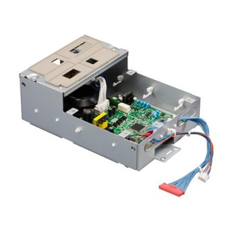
- Page 1 Super G3 FAX Board-T1 Installation Procedure Follow the instructions herein when installing the Super G3 FAX Board-T1 E N G L I S H to its host machine. PUB No.F-IM-6467-000 PRINTED IN JAPAN or CHINA...
-
Page 2: Unpacking And Checking The Components
1.1 Unpacking and Checking the Components 1.1.1 Checking the Contents In addition to this unit, you will need a fax panel unit (Fax Panel-A1) to enable the iR machine's fax functions. MEMO: If the machine is already equipped with an optional Inner 2-Way Tray-E1, you may skip the steps given for the mounting of the full state sensor unit. -
Page 3: Installation Procedure
1.2 Installation Procedure MEMO: If a LAN cover exits, 1) Remove the LAN cover [1]. 1.2.1 Installation Proce- - 4 screws [2]. dure 1) Turn off the main power switch, and disconnect the power plug from the power outlet. 2) Remove the machine's rear cover [1]. - 2 screws [2] F-1-4 4) Mount the modem PCB [1]. - Page 4 5) Fit the edge saddle [1] in place. 8) Fit the modem-NCU FFC [1] in place. - 2 connectors [2]. 9) Connect the modem-NCU cable [3]. - 2 connectors [4] 10) Connect the harness [5] of the speaker. - 1 connector [6] F-1-6 6) Fit the IP modem cable [1] in place.
- Page 5 13) Detach the lower cover [1] while shifting it in the direction of the arrow. When mounting the LAN cover [1], be sure to take - 5 screws [2] care not to break the grounding plate [3] by the LAN 14) Remove the upper right cover [3].
- Page 6 17) Remove the delivery tray [1]. - 2 screws [2] F-1-17 20) Lead the other NCU-PSU cable [2] through the F-1-15 machine's guide assembly [2]. 18) Fit the 2 wire saddles (white) [1] to the machine. F-1-18 21) Connect the NCU-PSU cable [1] (on the power F-1-16 supply side).
- Page 7 1.2.2 Mounting the Full 4) Mount the full state sensor unit [1] to the delivery assembly [2]. State Sensor Unit If a full state sensor unit already exits, you may skip the following steps: 1) Remove the front left cover [1] and the delivery cover [2].
- Page 8 1.2.3 After the Work 3) Put back the covers by reversing the steps used to remove them. 1) Cut of the area [2] of the rear cover [1] as shown us- MEMO: ing nippers. If you have mounted a full sensor unit, put back the covers identified as 3-1) through 3-3).
- Page 9 1.2.5 Attaching the Fax 3-6) Upper Right Cover 3-7) Lower Right Cover Approval label (EUR 3-8) Machine Rear Left Cover only) 3-9) Machine Rear Cover 4) Mount the drum unit to the machine. 1) Attach the Fax Approval label [1] firmly by posi- 5) Turn the developing assembly locking lever coun- tioning it against the indicated location of the ma- terclockwise.
-
Page 10: Checking The Operation
1.3 Checking the Operation 1.3.1 Setting the Type 1) Connect the iR machine's power plug to the power outlet, and turn on its main power switch. 2) In service mode, check to make sure that the type setting is set to the country or the region in which the machine will be used;...
Need help?
Do you have a question about the Super G3 FAX Board-T1 and is the answer not in the manual?
Questions and answers