Table of Contents
Advertisement
Quick Links
Advertisement
Chapters
Table of Contents

Subscribe to Our Youtube Channel
Related Manuals for KNF N680 EX


Summary of Contents for KNF N680 EX
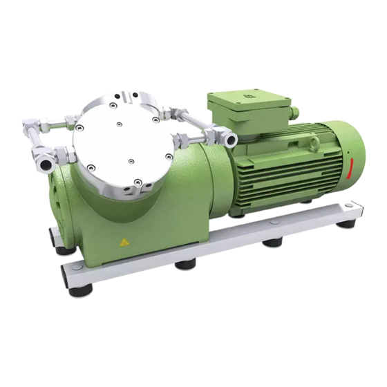
- Page 1 KNF 325438 02/22 N680 EX ATEX TRANSLATION OF ORIGINAL OPERATION AND INSTALLATION INSTRUCTION ENGLISH DIAPHRAGM PUMP Notice! Before operating the pump and accessories, read and observe the operating and installation instructions as well as the safety information!
-
Page 2: Table Of Contents
Index KNF Neuberger GmbH Alter Weg 3 1 About this document ............ 3 79112 Freiburg 1.1 Using the operating and installation instructions.. 3 Germany 1.2 Exclusion of liability........... 3 Tel. +49 (0)7664/5909-0 1.3 Symbols and markings.......... 4 Fax. +49 (0)7664/5909-99 2 Use ................... 6 2.1 Proper use .............. 6... -
Page 3: About This Document
à In the event of uncertainties with regard to the content of the operating and installation instructions, please contact the manufacturer (contact data: see www.knf.com). Please have the type and serial number of the pump ready. à Read the operating and installation instructions before you commission the pump. -
Page 4: Symbols And Markings
An activity to be carried out is specified here (a step). 1. The first step of an activity to be carried out is specified here. Follow other sequentially numbered steps. This symbol indicates important information. Translation of Original Operation and Installation Instruction, english, KNF 325438 02/22... - Page 5 Warning of explosive materials Warning of poisonous substances Warning of hand injuries through crushing Observe the operating instructions General mandatory sign Wear hearing protection Environmentally conscious disposal Tab.2 Explanations of pictograms Translation of Original Operation and Installation Instruction, english, KNF 325438 02/22...
-
Page 6: Use
Biological and microbiological substances § Explosives § Fibers § Foodstuffs. Pumps that can produce both vacuum as well as overpressure may not be used to simultaneously produce vacuum and overpressure. Translation of Original Operation and Installation Instruction, english, KNF 325438 02/22... -
Page 7: Use In Potentially Explosive Areas
The explosion protection designation can also be found at the following lo- cation: § Type plate of the pump Drive The pump motor must have at least the same explosion protection as the pump. Translation of Original Operation and Installation Instruction, english, KNF 325438 02/22... -
Page 8: Explanations Of The Explosion Protection Designation
Tab.4 Translation of Original Operation and Installation Instruction, english, KNF 325438 02/22... - Page 9 (or below) (see designation on the type plate) or that is not explosive and not combustible. Translation of Original Operation and Installation Instruction, english, KNF 325438 02/22...
- Page 10 An ignition hazard assessment in accordance with standards DIN EN ISO 80079-36 and DIN EN ISO 80079-37 was performed for the pumps. The protective goals were reached by applying ignition protection type con- structional safety "c". Translation of Original Operation and Installation Instruction, english, KNF 325438 02/22...
- Page 11 The pumps may not be set up outdoors. Commissioning may only be performed with suitable weather- and corrosion-protection paneling. § The pumps are to be set up so that they are not exposed to any UV ra- diation. Translation of Original Operation and Installation Instruction, english, KNF 325438 02/22...
-
Page 12: Safety
Therefore, during transport, during installation and during all work on the device in the potentially explosive atmosphere: § Only perform work when there is no possibility of a potentially explo- sive atmosphere. Translation of Original Operation and Installation Instruction, english, KNF 325438 02/22... - Page 13 EU/EC directives/standards See EC/EU Declaration of Conformity Customer service and repairs The pumps are maintenance-free. However, KNF recommends periodic in- spection of the pump for obvious changes in noise or vibration.
-
Page 14: Technical Data
Pneumatic connections Pump type Value N680.1.2 For hose Ø 18 Tab.11 *Acc. to ISO 228 Connection for water cooling Pump type Value N680.1.2 Hose ID9 Tab.12 *Acc. to ISO 228 Translation of Original Operation and Installation Instruction, english, KNF 325438 02/22... - Page 15 Max. installation altitude See operating instructions for drive Tab.14 Weight Pump type Value [kg] N680.1.2 Approx. 101 Tab.15 Coupling Parameter Value EX-designation II 2G h IIC T6…T4 Gb Size Tab.16 Translation of Original Operation and Installation Instruction, english, KNF 325438 02/22...
-
Page 16: Product Description And Function
2 Connection for water cooling 3 Pneumatic head con- nection 4 Pneumatic pump inlet 5 Motor 6 Motor fan cover 7 Electrical terminal box 8 Pneumatic pump outlet Fig.1 Design N680.1.2 EX Translation of Original Operation and Installation Instruction, english, KNF 325438 02/22... - Page 17 (2). In the upwards stroke, the diaphragm presses the medium out of the pump head via the outlet valve (1). The transfer chamber (3) is separated from the pump drive by the diaphragm. Translation of Original Operation and Installation Instruction, english, KNF 325438 02/22...
-
Page 18: Transport
Max. storage period (Aging, ball-bearing grease) [Mon.] Tab.17 Transport parameter and storage parameter Prior to commissioning, make sure that the pump has reached the ambient temperature (4 Techni- cal data). NOTICE Translation of Original Operation and Installation Instruction, english, KNF 325438 02/22... -
Page 19: Transporting With Lifting Eyebolt
3. Lift the pump out of the packaging with the aid of lifting gear. 4. Lower the pump carefully at the installation location. 5. Remove the transport eyebolt (2). 6. Screw the M12 screw (1) back into the thread. Translation of Original Operation and Installation Instruction, english, KNF 325438 02/22... -
Page 20: Installation And Connection
Store the pump at the installation site prior to installation to bring it up to the ambient temperature. à Mounting dimensions For mounting dimensions, see the following illustrations: Fig.5 Mounting dimensions N680.1.2 EX Translation of Original Operation and Installation Instruction, english, KNF 325438 02/22... - Page 21 Pump vibrations, in combination with adjacent components, can result in crushing and/or dam- WARNING age to these components. à Make sure that pump vibrations cannot lead to dangers in combination with adjacent com- ponents. Translation of Original Operation and Installation Instruction, english, KNF 325438 02/22...
-
Page 22: Electrical Connection
– the cables cannot be worn or damaged on sharp corners or edges – no tensile and pressure forces are exerted on the connection point of the cables (strain relief) Translation of Original Operation and Installation Instruction, english, KNF 325438 02/22... -
Page 23: Pneumatic Connection
2. Connect the suction line and the pressure line (for mounting dimen- sions, see Chapter 4 Technical data). 3. Lay the suction line and the pressure line at a downward angle to pre- vent condensate from running into the pump. Translation of Original Operation and Installation Instruction, english, KNF 325438 02/22... -
Page 24: Connecting Water Cooling (Optional)
à Safely drain the water discharge. The flow direction is allowed in both directions. Mounting dimensions For mounting dimensions, see the following dimensional drawings: Fig.6 Mounting dimensions N680.1.2 EX Translation of Original Operation and Installation Instruction, english, KNF 325438 02/22... -
Page 25: Operation
à Ensure that the pump outlet is not closed or restricted. Translation of Original Operation and Installation Instruction, english, KNF 325438 02/22... -
Page 26: Information On Switching The Pump On And Off
Do not operate the pump unless it is fully con- nected, or use a silencer. à Wear personal protection equipment (e.g., hearing protection). à Ensure that there is normal atmospheric pressure in the lines when switching on. Translation of Original Operation and Installation Instruction, english, KNF 325438 02/22... - Page 27 Recommissioning Before recommissioning, observe the applicable standards, guidelines, regulations and technical standards at the electrical connection. à Inspecting the pump Inspect the pump periodically for external damage or leakage. Translation of Original Operation and Installation Instruction, english, KNF 325438 02/22...
-
Page 28: Servicing
The validity of the CE conformity is rendered void if genuine spare parts are not used. à Use only genuine spare parts from KNF when performing servicing work. Translation of Original Operation and Installation Instruction, english, KNF 325438 02/22... - Page 29 It is the operator's responsibility to assess these factors. Translation of Original Operation and Installation Instruction, english, KNF 325438 02/22...
-
Page 30: Cleaning
With multi-headed pumps, parts of the various pump heads might become mixed up. à Change the parts of the individual pump heads that are to be replaced one at a time. Translation of Original Operation and Installation Instruction, english, KNF 325438 02/22... - Page 31 PTFE washer (for ST (16) 1 (per pump head) head only) Tab.20 * According to spare parts list, Chapter 11.1 Spare parts ** According to Individual parts of the pump head Translation of Original Operation and Installation Instruction, english, KNF 325438 02/22...
- Page 32 2. This helps to avoid incorrect assembly later. 4. Loosen the six hexagon socket head cap screws (1). Remove the head plate (3) and intermediate plate (18). Translation of Original Operation and Installation Instruction, english, KNF 325438 02/22...
- Page 33 Fit the new diaphragm (17) on the conrod plate (14); make certain that the inner beads on the outer and inner circumference of the diaphragm are seated in the grooves of the housing and conrod plate. Translation of Original Operation and Installation Instruction, english, KNF 325438 02/22...
- Page 34 7. On the suction side, assemble the new reed valve together with the valve stopper (tightening torque for screw (7): 1.5 Nm). 8. For two-headed pumps: Perform steps 1 to 4 for the second pump head. Translation of Original Operation and Installation Instruction, english, KNF 325438 02/22...
- Page 35 Risk of explosion from leaks à Before recommissioning the pump, check the pump heads and pneumatic connections for WARNING leaks. Leaks may lead to a risk of explosion. Translation of Original Operation and Installation Instruction, english, KNF 325438 02/22...
-
Page 36: Checking And Replacing Sprocket On Coupling
Tool/material Feeler gage 3 mm Test adapter for coupling (see Chapter 11.2 Accessories) 16mm open-end wrench with torque indicator Tab.22 Spare parts Spare part Item designation Quantity Sprocket Tab.23 Translation of Original Operation and Installation Instruction, english, KNF 325438 02/22... - Page 37 2. Loosen the nuts (1) that connect the motor (3) to the compressor housing (7). 3. Remove the ribbed disks (2). 4. Remove the motor (3) from the compressor housing (7). Translation of Original Operation and Installation Instruction, english, KNF 325438 02/22...
- Page 38 Make certain that the inner diameter of the ribbed disk (2) lies against the nut (1) and the outer diameter lies against the motor flange (3) (see Fig. 11). Fig.11 Alignment of the ribbed disk (2) Translation of Original Operation and Installation Instruction, english, KNF 325438 02/22...
- Page 39 – Disconnect the pump electrically and pneumatically again. 7. Pump integrated in application – Connect the suction and pressure sides to the pump. – Electrically connect the pump. – Test the functionality of the pump. Translation of Original Operation and Installation Instruction, english, KNF 325438 02/22...
-
Page 40: Troubleshooting
Install the pump at the highest location in the sys- tem. à Diaphragm or reed valves are Change the diaphragm and the reed valves worn. (see Chapter 9 Servicing). Tab.24 Translation of Original Operation and Installation Instruction, english, KNF 325438 02/22... - Page 41 Pump exhibiting changed running noises and vibrations Cause Troubleshooting à Pump bearing worn or defective. Determine the cause. à Contact KNF Customer Service. à Motor worn or defective. See operating instructions for the motor. Tab.26 Translation of Original Operation and Installation Instruction, english, KNF 325438 02/22...
- Page 42 2. Clean the pump (see Chapter 9.2.2 Cleaning the pump). 3. Send the pump together with completed Health and Safety Clearance and Decontamination Form to KNF, specifying the pumped medium. Translation of Original Operation and Installation Instruction, english, KNF 325438 02/22...
-
Page 43: Spare Parts And Accessories
Wrench for retainer plate 128753 Test adapter for coupling 322339 Corrugated hose for pneumatic con- 333224 nection; Length 500 mm Corrugated hose, certified for pneu- 333226 matic connection; Length 500 mm Tab.30 Translation of Original Operation and Installation Instruction, english, KNF 325438 02/22... -
Page 44: Returns
Returns KNF shall undertake to repair the pump only under the condition that the customer presents a certificate regarding the medium that is pumped and the cleaning of the pump. Please follow the instructions at knf.com/repairs here. -
Page 45: Appendix
Diaphragm pump N680 EX Appendix 13 Appendix à 13.1 Declaration of Conformity à 13.2 Motor à 13.3 Coupling 13.1 Declaration of Conformity For further information, see also § Konformitätserklärung N680EX.pdf Translation of Original Operation and Installation Instruction, english, KNF 325438 02/22... -
Page 50: Motor
Appendix Diaphragm pump N680 EX 13.2 Motor For further information, see also § Betriebsanleitung Motor.pdf § Konformitätserklärung Motor.pdf Translation of Original Operation and Installation Instruction, english, KNF 325438 02/22... - Page 51 Table of contents 2021-05-31 Operating manual Electric motors Size 63 - 225 ATEX / IECEx Doc-ID: 6316 Read the operating manual before starting all work.
- Page 52 © Herforder Elektromotoren-Werke GmbH & Co. KG Goebenstr. 106 D-32051 Herford Tel.: +49 (0) 5221 5904-0 Fax: +49 (0) 5221 5904-34 E-Mail: info@hew-hf.de Internet: www.hew-hf.de Release: Created by: Kothes! Technische Kommunikation GmbH & Co. KG www.kothes.de This issue replaces all previous issues. All previous issues are invalid.
- Page 53 Electric motors Size 63 - 225 ATEX / IECEx Table of contents General information ............... 5 Information on this operating manual ......5 Explanation of symbols ..........6 Limitation of liability ............7 Copyright ................ 8 Spare parts ..............8 Warranty conditions ............
- Page 54 Electric motors Size 63 - 225 ATEX / IECEx Table of contents Installation and commissioning .........32 Safety ................32 Installation ..............34 6.2.1 Ventilation at the location for use ....34 6.2.2 Types of construction as per EN 60034-7 ..34 6.2.3 Erecting the machine ........37 6.2.4 Installation .............37 Connecting to the energy supply .........38...
-
Page 55: General Information
Electric motors Size 63 - 225 ATEX / IECEx General information Pos : 1.1 /KN2006- SM/Allgemei nes /100 1 Allgemeines _Titel @ 8\mod_1142088318714_1.doc @ 75727 1 General information Pos : 1.2 /KN2006- SM/Allgemei nes /110 1.1 Informati onen z ur Anl eitung (Maschi ne) @ 40\mod_1182336499793_1.doc @ 495957 1.1 Information on this operating manual This operating manual makes it possible to handle the machine safely and efficiently. -
Page 56: Explanation Of Symbols
Electric motors Size 63 - 225 ATEX / IECEx General information Pos : 1.5 /KN2006- SM/Allgemei nes /120 1.1 Symboler kl ärung @ 8\mod_1142089345047_1.doc @ 75774 1.2 Explanation of symbols Safety instructions The safety instructions in this manual are indicated by symbols. The safety instructions are introduced by signal words which express the extent of the risk. -
Page 57: Limitation Of Liability
Electric motors Size 63 - 225 ATEX / IECEx General information Pos : 1.7 /KN2006- SM/Allgemei nes /121 1.1.1 Bes ondere Sic her heitshi nweis e_Titel @ 8\mod_1142090242324_1.doc @ 75783 Special safety instructions The following symbols are used in safety instructions in order to point out particular hazards. -
Page 58: Copyright
Electric motors Size 63 - 225 ATEX / IECEx General information Pos : 1.15 /KN 2006-SM /Allgemeines/140 1.1 Ur heberschutz @ 8\mod_1142092015791_1.doc @ 75819 1.4 Copyright This operating manual is protected by copyright and for internal use only. The manual must not be made available to third parties, reproduced in any way (including excerpts), its content must not be utilised and/or communicated without the written approval of the manufacturer, except for internal purposes. -
Page 59: Safety
Electric motors Size 63 - 225 ATEX / IECEx Safety Pos : 2.1 /F I/..Seitenumbr uch ..@ 0\mod272_1.doc @ 1522 Pos : 2.2 /KN2006- SM/Sic herheit/001 1 Sic her hei t_Titel @ 8\mod_1142425976781_1.doc @ 77461 2 Safety Pos : 2.3 /KN2006- SM/Sic herheit/001 1.0 Einführung @ 8\mod_1142427208593_1.doc @ 77470 This section provides you with an overview of all important aspects of safety required for providing staff with optimum protection as well as safe, fault-free operation. -
Page 60: Staff Requirements
Electric motors Size 63 - 225 ATEX / IECEx Safety and the safety of employees who may be at risk from a potentially explosive atmosphere. This includes adherence to further organisational measures, such as: ⚫ marking potentially explosive areas. ⚫ drawing up an explosion protection document for each zone. - Page 61 Electric motors Size 63 - 225 ATEX / IECEx Safety ◼ Trained person has been informed of the tasks with which he has been entrusted and the possible risks in case of incorrect behaviour in training measures provided by the user. ◼...
-
Page 62: Unauthorised Parties
Electric motors Size 63 - 225 ATEX / IECEx Safety Pos : 2.17 /KN 2006-SM /Sic her hei t/004 Pers onal/004 1.1.1 U nbefugte @ 13\mod_1152892272765_1.doc @ 148636 2.2.2 Unauthorised parties WARNING! Danger for unauthorised parties. Unauthorised persons who do not meet with the requirements described here, are not familiar with the hazards in the working area. -
Page 63: Personal Safety Equipment And Clothing
Electric motors Size 63 - 225 ATEX / IECEx Safety WARNING! Danger from improper use. Improper use of the machine can cause dangerous situations. Take particular care not to use the machine as follows: – Operation beyond the original designated application. -
Page 64: Special Hazards
Electric motors Size 63 - 225 ATEX / IECEx Safety Pos : 2.28 /KN 2006-SM /Sic her hei t/006 Pers önliche Schutz ausstattung/006 1.1.0_2 Bei bes onderen Ar beiten z u tragen_Titel @ 8\mod_1143361122656_1.doc @ 80999 To be worn for special tasks When carrying out special tasks, special safety equipment and clothing is required. - Page 65 Electric motors Size 63 - 225 ATEX / IECEx Safety Pos : 2.35 /KN 2006-SM /Sic her hei t/007 Besondere Gefahr en/El ektrisc her Strom_Gefahr! @ 8\mod_1143366795746_1.doc @ 81188 Electrical current DANGER! Danger to life from electrical current. There is an immediate risk of fatal injury in case of contact with live parts.
- Page 66 Electric motors Size 63 - 225 ATEX / IECEx Safety Pos : 2.39 /KN 2006-SM /Sic her hei t/007 Besondere Gefahr en/Heiß e Oberfl äc hen_Vorsicht! @ 8\mod_1143375956657_1.doc @ 81347 Hot surfaces CAUTION! Risk of burns from hot surfaces. Contact with hot parts can cause burns. Therefore: –...
-
Page 67: Safety Devices
Electric motors Size 63 - 225 ATEX / IECEx Safety Pos : 2.45 /KN 2006-Pr ojekte/Herforder Elektromotoren-Wer ke/Sic herheit/008 1.1 Sic her heitsei nrichtungen_Titel @ 59\mod_1203337625484_1.doc @ 1037161 2.6 Safety devices Pos : 2.46 /KN 2006-SM /Sic her hei t/008 Sicherheits einric htungen/Kein eigener Not-Aus (M asc hine) @ 41\mod_1183384960738_1.doc @ 503378 Integration into an emergency stop The machine is for use within a plant. -
Page 68: How To Act In Case Of Hazards And Accidents
Electric motors Size 63 - 225 ATEX / IECEx Safety Switch secured with a padlock Securing the machine to prevent it from being switched back on: …….. at ..h. Switch off the energy supply. DO NOT SWITCH ON If possible, secure the switch with a padlock and attach a The padlock must only be removed clearly visible sign according to Fig. -
Page 69: Environmental Protection
Electric motors Size 63 - 225 ATEX / IECEx Safety Pos : 2.52 /KN 2006-SM /Sic her hei t/011 U mweltsc hutz/011 U mwelts chutz Titel und Einführung @ 9\mod_1143987199086_1.doc @ 84175 2.9 Environmental protection CAUTION! Risk of environmental damage in case of incorrect handling. -
Page 70: Technical Data
Electric motors Size 63 - 225 ATEX / IECEx Technical data Pos : 3.2 /KN2006- SM/T echnisc he D aten/001 1 Tec hnisc he Daten_Ti tel @ 8\mod_1143124628960_1.doc @ 80561 3 Technical data Pos : 3.3 /KN2006- Proj ekte/H erfor der El ektromotoren- Wer ke/T ec hnis che D aten/HIN WEIS - Die notwendigen tec hnischen D aten @ 59\mod_1203077215350_1.doc @ 1034411 NOTE! The necessary technical data can be found on the respective type plates. -
Page 71: Explosion Protection Marking
Electric motors Size 63 - 225 ATEX / IECEx Technical data Pos : 3.10 /KN 2006-SM /nL---------- Abschnitts ende ---------- @ 8\mod_1141997892953_0.doc @ 75471 s: 3.11 /KN 2006-Pr ojekte/H erforder Elektr omotor en- Wer ke/Technisc he Daten/ATEX/009 1.1 Ex-Kennz eic hnung @ 60\mod_1203497200012_1.doc @ 1039729 3.3 Explosion protection marking EXPLOSION PROTECTION! acc. - Page 72 Electric motors Size 63 - 225 ATEX / IECEx Technical data Section Designation Significance Explosion protection symbol Marking for protection from explosions Device group Device group II. The motor can be used in potentially explosive areas except in mining. Category For application in Zone 1 and Zone 21 …...
-
Page 73: Construction And Function
Electric motors Size 63 - 225 ATEX / IECEx Construction and function Pos : 4.2 /KN2006- SM/Aufbau und F unktion/001 1 Aufbau und F unkti on_Titel @ 8\mod_1143713625726_1.doc @ 83161 4 Construction and function Pos : 4.3 /KN2006- Proj ekte/H erfor der El ektromotoren- Wer ke/Aufbau und F unktion/AT EX/002 1.1.0 Übersicht @ 68\mod_1209358678629_1.doc @ 1157152 4.1 Overview of sizes 63 to 132 15 16 Fig. -
Page 74: Overview Of Sizes 160 To 225
Electric motors Size 63 - 225 ATEX / IECEx Construction and function 4.2 Overview of sizes 160 to 225 17 18 Fig. 6: Overview of sizes 160 to 225 Flange rings 12 Terminal box cover seal Sealing rings DS* 13 Terminal box cover Cover plate DS* 14 Screwed cable glands Rolling bearings DS*... -
Page 75: Connection, Motor Protection
Electric motors Size 63 - 225 ATEX / IECEx Construction and function Pos : 4.5 /KN2006- SM/Aufbau und F unktion/005 1.1 Anschl üss e_Titel @ 9\mod_1144394868217_1.doc @ 86353 4.3 Connection, motor protection Pos : 4.6 /KN2006- Proj ekte/H erfor der El ektromotoren- Wer ke/Aufbau und F unktion/005 1.1.0 Ansc hlüss e @ 54\mod_1196341904624_1.doc @ 832892 Before connecting the explosion protected motor, check the following: do the ratings on the type plate match the mains voltage and frequency? does the explosion protection match the environment in which the motor is operated... -
Page 76: Operation On The Frequency Converter
Electric motors Size 63 - 225 ATEX / IECEx Construction and function 4.5 Operation on the frequency converter The motors of EX versions “pressure-proof encapsulation” Ex d(e) and “protection by housing” Ex t are approved for inverter operation. For approved versions, the possible frequency range must be obtained from the EU prototype test certificate. -
Page 77: Transportation, Packaging And Storage
Electric motors Size 63 - 225 ATEX / IECEx Transportation, packaging and storage Pos: 5.2 /KN2006-SM/Transport, Verpackung und Lagerung/001 1 Transport, Verpackung und Lagerung_Titel @ 9\mod_1144048567385_1.doc @ 84502 5 Transportation, packaging and storage Pos : 5.3 /KN2006- SM/Trans por t, Ver pac kung und Lag erung/002 1.1.0 War nung! Lebensgefahr durch sc hwebende Las ten @ 9\mod_1144048709603_1.doc @ 84516 Suspended loads WARNING! Risk of fatal injury from suspended loads. -
Page 78: Delivery Inspection
Electric motors Size 63 - 225 ATEX / IECEx Transportation, packaging and storage Pos : 5.7 /KN2006- SM/Trans por t, Ver pac kung und Lag erung/002 1.1.0 Vorsic ht Tr ansportsc häden bei unsac hgemäß em Trans por t_Vorsic ht!Sac hsc haden @ 9\mod_1144051344560_1.doc @ 84538 Improper transportation CAUTION! Risk of damage in case of improper... -
Page 79: Transportation
Electric motors Size 63 - 225 ATEX / IECEx Transportation, packaging and storage Pos : 5.14 /KN 2006-SM /Transport, Verpac kung und Lager ung/006 1.1 Transport_Titel @ 9\mod_1145448098995_1.doc @ 90988 5.2 Transportation Pos : 5.15 /KN 2006-Pr ojekte/Herforder Elektromotoren-Wer ke/Trans port/005 1.1.0 Ansc hl agpunkte @ 54\mod_1196342213558_1.doc @ 832949 ◼... -
Page 80: Packaging
Electric motors Size 63 - 225 ATEX / IECEx Transportation, packaging and storage Pos : 5.21 /KN 2006-SM /Transport, Verpac kung und Lager ung/006 1.1.0 Transport von Pal etten mit dem Gabels tapl er @ 9\mod_1144392667613_1.doc @ 86319 Transporting pallets by forklift Packages which are fastened to pallets can be transported by forklift under the following conditions: ◼... -
Page 81: Storage
Electric motors Size 63 - 225 ATEX / IECEx Transportation, packaging and storage Pos : 5.28 /KN 2006-SM /Transport, Verpac kung und Lager ung/007 1.1 Lagerung_Ti tel @ 38\mod_1179315679426_1.doc @ 471241 5.4 Storage Pos : 5.29 /KN 2006-Pr ojekte/Herforder Elektromotoren-Wer ke/Trans port/007 1.1.0 Lager ung der Pac ks tüc ke @ 59\mod_1203074612840_1.doc @ 1034278 Storing packages Store the packages under the following conditions: ◼... -
Page 82: Installation And Commissioning
Electric motors Size 63 - 225 ATEX / IECEx Installation and commissioning Pos : 6.2 /KN2006- SM/Installation & Inbetri ebnahme/001 1 Ins tall ati on und Ers tinbetriebnahme_Titel @ 9\mod_1144393592402_1.doc @ 86332 6 Installation and commissioning Pos : 6.3 /KN2006- Proj ekte/H erfor der El ektromotoren- Wer ke/Ins tall ation & Inbetriebnahme/AT EX/HIN WEIS - Nor men, Ric htlini en Ex- Ber eich @ 60\mod_1203665634793_1.doc @ 1043962 NOTE! When installing and commissioning adhere to the current standards and directive for electrical... - Page 83 Electric motors Size 63 - 225 ATEX / IECEx Installation and commissioning Pos : 6.12 /KN 2006-SM /Installati on & Inbetriebnahme/003 1.1.0 El ektrisc he Anl age_Gefahr! @ 9\mod_1144397463440_1.doc @ 86395 Electrical equipment DANGER! Danger to life from electrical current. There is a risk of fatal injury from contact with live parts.
-
Page 84: Installation
Electric motors Size 63 - 225 ATEX / IECEx Installation and commissioning Pos : 6.18 /KN 2006-SM /Installati on & Inbetriebnahme/005 1.1 Installation_Titel @ 9\mod_1144401700720_1.doc @ 86426 6.2 Installation Pos : 6.19 /KN 2006-Pr ojekte/Herforder Elektromotoren-Wer ke/Installation & Inbetri ebnahme/1.1.1 Bel üftung am Einsatzort @ 59\mod_1203072994994_1.doc @ 1034256 6.2.1 Ventilation at the location for use The ventilation for the motor must not be obstructed. - Page 85 Electric motors Size 63 - 225 ATEX / IECEx Installation and commissioning Type of Symbol Explanation construction ◼ IM B7 2 bearing covers IM 1061 ◼ with feet ◼ Construction type IM B3 ◼ Fastening on the wall ◼ Feet right, viewed from drive side ◼...
- Page 86 Electric motors Size 63 - 225 ATEX / IECEx Installation and commissioning Type of Symbol Explanation construction ◼ IM V18 2 bearing covers IM 3611 ◼ without feet ◼ Shaft end bottom ◼ Securing flange type C ◼ IM V19 2 bearing covers IM 3631 ◼...
-
Page 87: Erecting The Machine
Electric motors Size 63 - 225 ATEX / IECEx Installation and commissioning Pos : 6.23 /KN 2006-Pr ojekte/Herforder Elektromotoren-Wer ke/Installation & Inbetri ebnahme/1.1.1 M aschi nenaufstellung @ 59\mod_1203075619986_1.doc @ 1034390 6.2.3 Erecting the machine DANGER! Risk of death due to insufficient protection classes. -
Page 88: Connecting To The Energy Supply
Electric motors Size 63 - 225 ATEX / IECEx Installation and commissioning Pos : 6.26 /KN 2006-SM /nL---------- Abschnitts ende ---------- @ 8\mod_1141997892953_0.doc @ 75471 Pos : 6.27 /KN 2006-Pr ojekte/Herforder Elektromotoren-Wer ke/Installation & Inbetri ebnahme/006 1.1 Elektrischer Ans chl uss _Titel @ 59\mod_1203082082094_1.doc @ 1034835 6.3 Connecting to the energy supply Pos : 6.28 /KN 2006-SM /Sic her hei t/007 Besondere Gefahr en/El ektrisc her Strom_Gefahr! @ 8\mod_1143366795746_1.doc @ 81188 Electrical current... -
Page 89: Voltage And Circuit
Electric motors Size 63 - 225 ATEX / IECEx Installation and commissioning Ex d motors Connection to the terminal box with these motors is implemented with a standard connection. You must take great care when selecting the cable connection. It is imperative that the version is approved and approved for at least the protection class of the motor. -
Page 90: Checking The Insulation Resistance
Electric motors Size 63 - 225 ATEX / IECEx Installation and commissioning Pos : 6.34 /KN 2006-Pr ojekte/Herforder Elektromotoren-Wer ke/Installation & Inbetri ebnahme/1.1.1 Is ol ations wi ders tand pr üfen @ 59\mod_1203315508128_1.doc @ 1036431 6.3.3 Checking the insulation resistance ◼... - Page 91 Electric motors Size 63 - 225 ATEX / IECEx Installation and commissioning Pos : 6.39 /KN 2006-Pr ojekte/Herforder Elektromotoren-Wer ke/Installation & Inbetri ebnahme/VOR SICHT - Her ausg esc hleuderte Pas sfeder @ 59\mod_1203079038551_1.doc @ 1034432 CAUTION! Risk of personal injury and/or material damage from feather keys ejected at speed.
-
Page 92: Operations
Electric motors Size 63 - 225 ATEX / IECEx Operations Pos : 7.2 /KN2006- SM/Bedienung/001 1 Bedi enung _Titel @ 9\mod_1144402040153_1.doc @ 86490 7 Operations Pos : 7.3 /KN2006- Proj ekte/H erfor der El ektromotoren- Wer ke/Bedienung/1.1 Allgemei nes @ 59\mod_1203412166172_1.doc @ 1038421 7.1 General information During operation no staff are required in the machine area or in the direct vicinity to operate it. -
Page 93: Faults
Electric motors Size 63 - 225 ATEX / IECEx Faults Pos : 8.2 /KN2006- SM/Stör ung en/001 1 Stör ung en_Titel+Text @ 9\mod_1144439647801_1.doc @ 86957 8 Faults The following chapter describes possible causes of faults and the work to eradicate them. In case of faults which occur several times, reduce the maintenance interval accordingly to suit the actual strain. - Page 94 Electric motors Size 63 - 225 ATEX / IECEx Faults Pos : 8.10 /KN 2006-SM /Störungen/003 1.1.0 Elektrisc he Anlage_Gefahr! @ 9\mod_1144439649994_1.doc @ 86978 Electrical equipment DANGER! Danger to life from electrical current. There is a risk of fatal injury from contact with live parts.
-
Page 95: Fault Table
Electric motors Size 63 - 225 ATEX / IECEx Faults Pos : 8.16 /KN 2006-SM /Störungen/003 1.1.0 Verhalten bei Stör ung en (Ger ät) @ 9\mod_1144441786782_1.doc @ 87239 How to act in case of faults The following basic instructions apply: In case of faults which pose an immediate risk to people or objects of material value, activate the emergency stop function immediately. - Page 96 Electric motors Size 63 - 225 ATEX / IECEx Faults Fault Possible cause Remedy To be remedied by ◼ Bearing noises Scoring on inner bearing Replace bearing, avoid Manufacturer ring, e.g. from motor vibrations when at a starting up with bearing standstill locked ◼...
-
Page 97: Commissioning After Remedied Fault
Electric motors Size 63 - 225 ATEX / IECEx Faults Pos: 8.21 /KN2006-SM/Störungen/007 1.1 Inbetriebnahme nach behobener Störung_Titel @ 9\mod_1144442691882_1.doc @ 87274 8.3 Commissioning after remedied fault Pos : 8.22 /KN 2006-SM /Störungen/007 1.1.0 Inbetriebnahme nac h behobener Störung --> Standard --> ggf. anpass en @ 9\mod_1144442763671_1.doc @ 87281 After remedying the fault carry out the following steps for re- commissioning: Reset the emergency stop devices. -
Page 98: Maintenance
Electric motors Size 63 - 225 ATEX / IECEx Maintenance Pos : 9.2 /KN2006- SM/War tung/001 1 Wartung_Titel @ 9\mod_1144434830143_1.doc @ 86796 9 Maintenance Pos : 9.3 /KN2006- SM/War tung/002 1.1 Sic herheit_Titel @ 9\mod_1144434831619_1.doc @ 86810 9.1 Safety Pos: 9.4 /KN2006-SM/Wartung/003 1.1.0 Personal --> Standard --> ggf. anpassen @ 9\mod_1144434832402_1.doc @ 86817 ◼... - Page 99 Electric motors Size 63 - 225 ATEX / IECEx Maintenance Pos : 9.10 /KN 2006-SM /Wartung/003 1.1.0 Elektrisc he Anlage @ 9\mod_1144434833265_1.doc @ 86824 Electrical equipment DANGER! Danger to life from electrical current. There is a risk of fatal injury from contact with live parts.
-
Page 100: Cleaning
Electric motors Size 63 - 225 ATEX / IECEx Maintenance ◼ At all lubricating points which are supplied with lubricant by hand, remove the expelled, used or excess grease and dispose of it in accordance with the local regulations. Pos : 9.18 /KN 2006-SM /Wartung/004 1.1.0.0 Ents orgung Öl @ 9\mod_1144439240623_1.doc @ 86943 ◼... - Page 101 Electric motors Size 63 - 225 ATEX / IECEx Maintenance In case you have any questions on maintenance work and intervals, contact the manufacturer, see service address on page 2. Pos : 9.26 /KN 2006-SM /nL---------- Abschnitts ende ---------- @ 8\mod_1141997892953_0.doc @ 75471 Pos : 9.27 /KN 2006-Pr ojekte/Herforder Elektromotoren-Wer ke/Wartung/006 1.1.0 Wartungsplan @ 54\mod_1196342707944_1.doc @ 833101 The standard version motors are fitted with permanently lubricated bearings.
-
Page 102: Tightening Torque Values For Screws
Electric motors Size 63 - 225 ATEX / IECEx Maintenance Pos : 9.29 /KN 2006-Pr ojekte/Herforder Elektromotoren-Wer ke/Wartung/1.1 Sc hraubenanz ugsdr ehmomente @ 67\mod_1208937207889_1.doc @ 1150009 9.4 Tightening torque values for screws Explosion protection EXPLOSION PROTECTION! The introduction of ignition sources such as sparks, open flames and hot surfaces can cause explosions in the potentially explosive area. -
Page 103: Screw Connections, Property Class 8.8 And A4-70
Electric motors Size 63 - 225 ATEX / IECEx Maintenance 9.4.2 Screw connections, property class 8.8 and A4-70 NOTE! Only use tightening torque values for screws of property class 8.8 and A4-70 (A4-80) in high- strength parts (e.g. grey cast iron, steel). Thread Tightening torque Thread... -
Page 104: Measures On Completion Of Maintenance
Electric motors Size 63 - 225 ATEX / IECEx Maintenance Pos : 9.31 /KN 2006-SM /Wartung/009 1.1 M aß nahmen nac h erfolgter Wartung_Titel @ 9\mod_1144438930025_1.doc @ 86928 9.5 Measures on completion of maintenance Pos : 9.32 /KN 2006-Pr ojekte/Herforder Elektromotoren-Wer ke/Wartung/AT EX/007 1.1.0 Potential ausgleich und Erdung anbring en EX-SCHUTZ @ 60\mod_1203501310249_1.doc @ 1040296 Explosion protection EXPLOSION PROTECTION! Introducing ignition sources such as sparks in the... -
Page 105: Removal
Electric motors Size 63 - 225 ATEX / IECEx Removal Pos : 10.2 /KN 2006-SM /Demontag e/001 1 D emontage_Titel @ 9\mod_1144501489239_1.doc @ 87445 10 Removal Pos : 10.3 /KN 2006-SM /Demontag e/001 1.0 N ac hdem das Gebrauchsende erreic ht ist...(Mas chi ne) @ 41 \mod_1183385607485_1.doc @ 503412 Once the period of use has expired, the machine must be removed and disposed of in an environmentally friendly manner. -
Page 106: Removal
Electric motors Size 63 - 225 ATEX / IECEx Removal Pos : 10.12 /KN 2006-SM/D emontage/003 1.1.0 Gr undleg endes @ 9\mod_1144870287285_1.doc @ 89626 Improper removal WARNING! Risk of injury from improper removal. Stored residual energy, sharp parts, points and corners on and in the device or on the required tools can cause injuries. -
Page 107: Disposal
Electric motors Size 63 - 225 ATEX / IECEx Removal Pos : 10.16 /KN 2006-SM/D emontage/009 1.1 Ents orgung --> Standar d --> ggf. anpas sen! @ 8\mod_1142093514566_1.doc @ 75855 10.3 Disposal If no agreements have been made for return or disposal, have the dismantled components recycled: ◼... - Page 108 EC / EU – declaration of conformity HERFORDER ELEKTROMOTOREN-WERKE GmbH & Co. KG D – 32051 Herford Goebenstraße 106 Tel.: 05221 59040 info@HEW-HF.de D – 32008 Herford post office box 1852 Electrical operating equipment: Explosion-proof three phase asynchronous motors ( flame-proof encapsulation ) with squirrel cage marking gas marking dust DCEx 63...
- Page 109 Diaphragm pump N680 EX Appendix 13.3 Coupling For further information, see also § Rotex-BA.pdf Translation of Original Operation and Installation Instruction, english, KNF 325438 02/22...
- Page 110 KTR-N 40210 EN ® ROTEX Sheet: 1 of 27 Operating/Assembly instructions Edition: ® ROTEX Torsionally flexible jaw couplings type No. 001 - shaft coupling, No. 018 - DKM, with taper clamping sleeve and their combinations according to directive 2014/34/EU Type No. 001 - shaft coupling Type No.
- Page 111 KTR-N 40210 EN ® ROTEX Sheet: 2 of 27 Operating/Assembly instructions Edition: ® ROTEX is a torsionally flexible jaw coupling. It is able to compensate for shaft misalignment, for example caused by manufacturing inaccuracies, thermal expansion, etc. Table of contents Technical data Advice General advice...
-
Page 112: Technical Data
KTR-N 40210 EN ® ROTEX Sheet: 3 of 27 Operating/Assembly instructions Edition: Technical data ® Illustration 1: ROTEX (material: powder metal, Al-D and Al-H) Table 1: Material powder metal steel (Sint) Spider (component 2) Dimensions [mm] Com- Size Rated torque [Nm] General Finish bore ponent... - Page 113 KTR-N 40210 EN ® ROTEX Sheet: 4 of 27 Operating/Assembly instructions Edition: Technical data ® Illustration 2: ROTEX (material: GJL/GJS) Table 4: Material cast iron (GJL)/nodular iron (GJS) Spider (component 2) Dimensions [mm] Rated torque [Nm] Com- General Size Finish bore ponent d (min-max) 92 ShA...
- Page 114 KTR-N 40210 EN ® ROTEX Sheet: 5 of 27 Operating/Assembly instructions Edition: Technical data ® Illustration 3: ROTEX (material: steel) Table 5: Material steel Dimensions [mm] Spider (component 2) Com- Rated torque [Nm] Size Finish bore General ponent 92 ShA 98 ShA 64 ShD d (min-max)
- Page 115 KTR-N 40210 EN ® ROTEX Sheet: 6 of 27 Operating/Assembly instructions Edition: Technical data ® Illustration 4: ROTEX type DKM Table 6: Type DKM Spider (component 2) Dimensions [mm] Size Rated torque [Nm] General Dimensions d, D, D 92 ShA 98 ShA 1280 1920...
-
Page 116: Advice
KTR-N 40210 EN ® ROTEX Sheet: 7 of 27 Operating/Assembly instructions Edition: Technical data Coupling design: Screwing on cam side Screwing on collar side Different combinations of types TB1 and TB2 are possible. ® Illustration 5: ROTEX type with taper clamping sleeve Table 7: Type with taper clamping sleeve Dimensions [mm] Spider... -
Page 117: Safety And Advice Symbols
KTR-N 40210 EN ® ROTEX Sheet: 8 of 27 Operating/Assembly instructions Edition: Advice 2.2 Safety and advice symbols This symbol indicates notes which may contribute to Warning of potentially explosive preventing bodily injuries or serious bodily injuries that atmospheres may result in death caused by explosion. This symbol indicates notes which may contribute to Warning of personal injury preventing bodily injuries or serious bodily injuries that... -
Page 118: Coupling Selection
KTR-N 40210 EN ® ROTEX Sheet: 9 of 27 Operating/Assembly instructions Edition: Advice 2.5 Coupling selection For a permanent and failure-free operation of the coupling it must be selected according to the selection instructions (according to DIN 740 part 2) for the particular application (see ®... -
Page 119: Assembly
KTR-N 40210 EN ® ROTEX Sheet: 10 of 27 Operating/Assembly instructions Edition: Assembly The coupling is generally supplied in individual parts. Before assembly the coupling has to be inspected for completeness. 4.1 Components of the coupling ® Components of ROTEX , shaft coupling type No. -
Page 120: Advice For Finish Bore
KTR-N 40210 EN ® ROTEX Sheet: 11 of 27 Operating/Assembly instructions Edition: Assembly 4.1 Components of the coupling Features of standard spiders 92 Shore A 98 Shore A 64 Shore D Spider hardness ® ® ® T-PUR T-PUR T-PUR (Shore) (orange) (yellow) (purple) -
Page 121: Assembly Of The Hubs
KTR-N 40210 EN ® ROTEX Sheet: 12 of 27 Operating/Assembly instructions Edition: Assembly 4.2 Advice for finish bore Table 9: Recommended fit pairs acc. to DIN 748-1 Bore [mm] Shaft tolerance Bore tolerance above up to (KTR standard) If a feather keyway is intended to be used in the hub, it should correspond to the tolerance ISO JS9 (KTR standard) with standard operating conditions or ISO P9 with complicated operating conditions (frequently alternating torsional direction, shock loads, etc.). -
Page 122: Assembly Of Taper Clamping Sleeve
KTR-N 40210 EN ® ROTEX Sheet: 13 of 27 Operating/Assembly instructions Edition: Assembly 4.3 Assembly of the hubs Illustration 10: Assembly of the hubs Illustration 11: Assembly of coupling 4.4 Assembly of taper clamping sleeve Assembly of taper clamping sleeve: Clean the contact surfaces of the taper clamping sleeves and of shaft and hub and afterwards apply thin fluid oil lightly (e. -
Page 123: Displacements - Alignment Of The Couplings
KTR-N 40210 EN ® ROTEX Sheet: 14 of 27 Operating/Assembly instructions Edition: Assembly 4.4 Assembly of taper clamping sleeve Disassembly of taper clamping sleeve: The taper clamping sleeve is released by removing the setscrews. Afterwards one of the setscrews used as forcing screw is screwed in the thread of the sleeve and tightened. - Page 124 KTR-N 40210 EN ® ROTEX Sheet: 15 of 27 Operating/Assembly instructions Edition: Assembly 4.5 Displacements - alignment of the couplings Examples of the displacement combinations Illustration 15: specified in illustration 15: Combinations of displacement Example 1: K = 30 % K = 70 % Example 2:...
-
Page 125: Start-Up
KTR-N 40210 EN ® ROTEX Sheet: 16 of 27 Operating/Assembly instructions Edition: Start-up Before start-up of the coupling, inspect the tightening of setscrews in the hubs, the alignment and the distance dimension E and adjust, if necessary, and also inspect all screw connections for the tightening torques specified. If used in potentially explosive atmospheres the setscrews to fasten the hubs as well as all screw connections must be secured against working loose additionally, e. -
Page 126: Breakdowns, Causes And Elimination
KTR-N 40210 EN ® ROTEX Sheet: 17 of 27 Operating/Assembly instructions Edition: Breakdowns, causes and elimination ® The below-mentioned failures can lead to a use of the ROTEX coupling other than intended. In addition to the specifications given in these operating/assembly instructions make sure to avoid such failures. The errors listed can only be clues to search for the failures. - Page 127 KTR-N 40210 EN ® ROTEX Sheet: 18 of 27 Operating/Assembly instructions Edition: Breakdowns, causes and elimination Hazard notes for Breakdowns Causes potentially explosive Elimination atmospheres 1) Set the unit out of operation Operating parameters 2) Review the operating parameters and select do not meet with the a bigger coupling (consider mounting space) performance of the...
-
Page 128: Disposal
KTR-N 40210 EN ® ROTEX Sheet: 19 of 27 Operating/Assembly instructions Edition: Disposal In respect of environmental protection we would ask you to dispose of the packaging resp. products on termination of their service life in accordance with the legal regulations and standards that apply. •... -
Page 129: Enclosure A
KTR-N 40210 EN ® ROTEX Sheet: 20 of 27 Operating/Assembly instructions Edition: Enclosure A Advice and instructions regarding the use in potentially explosive atmospheres Applicable hub designs/types: a) Hubs that may be used in group II, category 2 and 3 : ®... -
Page 130: Advice And Instructions Regarding The Use In Potentially Explosive Atmospheres
KTR-N 40210 EN ® ROTEX Sheet: 21 of 27 Operating/Assembly instructions Edition: Enclosure A Advice and instructions regarding the use in potentially explosive atmospheres 10.1 Intended use in potentially explosive atmospheres Conditions of operation in potentially explosive atmospheres ® ROTEX couplings are suitable for the use according to EU directive 2014/34/EU. -
Page 131: Inspection Intervals For Couplings In Potentially Explosive Atmospheres
KTR-N 40210 EN ® ROTEX Sheet: 22 of 27 Operating/Assembly instructions Edition: Enclosure A Advice and instructions regarding the use in potentially explosive atmospheres 10.2 Inspection intervals for couplings in potentially explosive atmospheres Equipment category Inspection intervals For couplings operated in zone 2 or zone 22 the inspection and maintenance intervals of the usual operating/assembly instructions for standard operation apply. - Page 132 KTR-N 40210 EN ® ROTEX Sheet: 23 of 27 Operating/Assembly instructions Edition: Enclosure A Advice and instructions regarding the use in potentially explosive atmospheres 10.2 Inspection intervals for couplings in potentially explosive atmospheres ® ROTEX coupling Illustration 17.1: ® ROTEX elements Illustration 17.2: ®...
-
Page 133: Standard Values Of Wear
KTR-N 40210 EN ® ROTEX Sheet: 24 of 27 Operating/Assembly instructions Edition: Enclosure A Advice and instructions regarding the use in potentially explosive atmospheres 10.3 Standard values of wear In case of backlash > X mm, the flexible spider/DZ elements must be replaced. The general condition of the coupling can both be monitored at standstill and during operation. -
Page 134: Marking Of Coupling For Potentially Explosive Atmospheres
KTR-N 40210 EN ® ROTEX Sheet: 25 of 27 Operating/Assembly instructions Edition: Enclosure A Advice and instructions regarding the use in potentially explosive atmospheres 10.4 marking of coupling for potentially explosive atmospheres ® The ATEX marking of the ROTEX coupling is applied on the outer sheath or on the front side. The flexible spider resp. - Page 135 KTR-N 40210 EN ® ROTEX Sheet: 26 of 27 Operating/Assembly instructions Edition: Enclosure A Advice and instructions regarding the use in potentially explosive atmospheres 10.4 marking of coupling for potentially explosive atmospheres Deviating marking applies until 31st October 2019: Short marking: II 2GD c IIC T X/I M2 c X ...
-
Page 136: Eu Certificate Of Conformity
KTR-N 40210 EN ® ROTEX Sheet: 27 of 27 Operating/Assembly instructions Edition: Enclosure A Advice and instructions regarding the use in potentially explosive atmospheres 10.5 EU Certificate of conformity EU Certificate of conformity corresponding to EU directive 2014/34/EU dated 26 February 2014 and to the legal regulations The manufacturer - KTR Systems GmbH, D-48432 Rheine - states that the ®... - Page 140 KNF worldwide You can find our local KNF partners at: www.knf.com...
Need help?
Do you have a question about the N680 EX and is the answer not in the manual?
Questions and answers