Sony WRT-805A Operating Instructions Manual
Uhf synthesized transmitter
Hide thumbs
Also See for WRT-805A:
- Operating instructions manual (48 pages) ,
- Operating instructions manual (48 pages)

Related Manuals for Sony WRT-805A


Summary of Contents for Sony WRT-805A
- Page 1 3-860-341-31(1) Synthesized Transmitter Operating Instructions WRT-805A © 1997 by Sony Corporation [AU66]...
-
Page 2: Table Of Contents
Table of Contents Precautions ................. 2 Settings ................11 Introduction ............... 3 Initiating Setting Mode ..........11 Features ................3 Changing the Channel Selection ........12 Channels and Carrier Frequencies ........5 Changing the Input Attenuation Setting ...... 13 Parts Identification ............6 Resetting the Accumulated Time Indication .... -
Page 3: Introduction
A 14-MHz frequency band (or two consecutive-numbered TV channels, such as 66 and 67 of the WRT-805A) is Remote battery alarm on tuner assigned to each microphone/transmitter and tuner model. - Page 4 Introduction Audio input connector (3.5-mm dia.) with locking LCD for coordinated operation control mechanism The LCD shows the current channel number, the residual The screw-type locking mechanism ensures reliable battery power, input attenuation setting, AF input level and connection. RF output. An accumulated operation time indication is also provided Compact helical antenna for simple control of the time of battery use (in 1-minute...
-
Page 5: Channels And Carrier Frequencies
Channels and Carrier Frequencies The WRT-805A can transmit on any selected wireless For channel selection, see “Changing the Channel channel among those listed below. Selection” on page 12. -
Page 6: Parts Identification
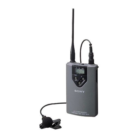
Parts Identification 1 POWER switch Turns the power of the transmitter ON or OFF. When you set this switch to ON without holding any other POWER switch button, the transmitter is set to normal Transmit mode and transmits the signal of the selected channel. Antenna When you set this switch to ON while holding the SET button down, Setting mode is initiated. - Page 7 b RF (antenna output) indication 3 SET button Lights when a signal is being transmitted from the antenna. In normal transmit mode, press this button to change the indication items in the lower half of the liquid-crystal c BATT (battery) indication display.
-
Page 8: Power Supply
Parts Identification 6 INPUT level switch Switch functions Select the reference input level appropriate for the connected audio source. – – –60 dBV: For a microphone –40 dBV: For an electric guitar ø — 7 PHASE switch Select the input phase appropriate for the connected audio 8 Belt clip source. - Page 9 Leakage left in the unit may cause poor battery contact. If there seems to be poor battery contact, consult your Sony dealer. When the battery reaches stage 3 shown in the table, the BATT indication on the WRR-800A/801A/850A also starts flashing.
-
Page 10: Connections
For the ATT level adjustment, see page 13. MP Guitar Cable. To connect a microphone GC-0.7 MP guitar cable (optional) When using one of the following optional Sony Electret Condenser Microphones equipped with a miniature phone plug, connect it as illustrated below. Sony Electret Condenser Microphones (optional):... -
Page 11: Notes On Microphone System Operation
Notes on Microphone System Operation Settings • To operate with 2 or more channels, maintain a distance of Initiating Setting Mode at least 30 cm (1 ft.) between each pair of transmitters. For details of operation with 2 or more channels, refer to In Setting mode, you can change the transmission channel the Operating Instructions for the WRR-800A/801A/850A and the attenuation level, or reset the accumulated time... -
Page 12: Changing The Channel Selection
Settings Once the desired channel number appears, set the Changing the Channel Selection POWER switch to OFF to release Setting mode. Or, press the SET button to continue operations in Setting Set the unit to Setting mode. mode. If the channel number is not displayed, press the SET The next time you turn on the power only by setting the button to obtain the channel number indication. -
Page 13: Changing The Input Attenuation Setting
The next time you turn on the power only by setting the Changing the Input Attenuation Setting POWER switch to ON, the transmitter will be set to Transmit mode with the selected attenuation setting. You can change the input attenuation setting in 3-dB steps in a range of 0 to 21 dB. -
Page 14: Resetting The Accumulated Time Indication
BATT BATT The time indication accumulates time in hours and minutes when the WRT-805A is on. Reset the indication to “00:00” whenever you replace the battery so that it can display the running time of the battery. Set the unit to Setting mode. -
Page 15: Specifications
(one LR6/size AA alkaline battery) Carrier frequencies 792.250 to 805.500 MHz Battery life Approx. 6 hours at 25°C or 77°F RF power output 10 mW (50-ohm load) with Sony LR6 alkaline battery Within ±0.002% Frequency stability Tone signal 32.768 kHz General Type of antenna -wavelength helical Operating temperature 0°C to +50°C (32°F to 122°F) - Page 16 Sony Corporation Printed in Japan...