Table of Contents
Advertisement
Quick Links
Advertisement
Table of Contents

Related Manuals for Sony WRT-822B


Summary of Contents for Sony WRT-822B
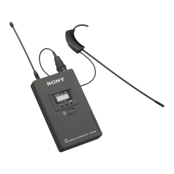
- Page 1 UHF SYNTHESIZED TRANSMITTER WRT-822B SERVICE MANUAL 1st Edition...
- Page 2 Ce manual est destiné uniquement aux personnes compétentes en charge de l’entretien. Afin de réduire les risques de décharge électrique, d’incendie ou de blessure n’effectuer que les réparations indiquées dans le mode d’emploi à moins d’être qualifié pour en effectuer d’autres. Pour toute réparation faire appel à une personne compétente uniquement. WRT-822B...
-
Page 3: Table Of Contents
3-2-11. Spurious Emissions Check ............3-13 4. Spare Parts 4-1. Notes on Repair Parts .................. 4-1 4-2. Exploded Views ..................4-2 4-3. Electrical Parts List ..................4-3 4-4. Supplied Accessories .................. 4-7 5. Semiconductor Pin Assignments ..........5-1 6. Block Diagram ..................6-1 WRT-822B... - Page 4 7. Board Layout MB-940 ....................... 7-1 8. Schematic Diagrams MB-940 ....................... 8-1 WRT-822B...
-
Page 5: Operating Instructions
Operating Instructions operating instructions 3-205-431-11 (1) Overview Features The WRT-822B is a transmitter for a UHF synthesized wireless microphone system to be used The features of the WRT-822B are: UHF Synthesized for broadcast or movie production purpose. This – Phase Locked Loop (PLL) synthesized system transmitter is suitable for Electronic News gathering –... - Page 6 Pressing the + button cycles the indication in the Lights whenever an audio signal stronger than the order shown in the tables in the “Sony Wireless reference level is received. Caution Microphone System Frequency List” supplied with...
-
Page 7: Service Overview
Insert the wire into notch of the front case and assembly the it. MB-940 Board Connector (S) 4P CN501 Battery Bracket (MC) CN102 Terminal CN501 Assy Spring, battery coil Battery Terminal Assy Knob (P) Gray Black White CN102 Gray White Black Case (upper) Case (upper) WRT-822B... -
Page 8: Notes On Parts Replacement
2-2. Notes on Parts Replacement 2-2-1. EEPROM (IC405) Replacement On the EEPROM (IC405) mounted on the MB-940 board, frequency data corresponding to each WRT-822B have been written. After replacing an EEPROM, it is necessary to write the corresponding frequency data to the new EEPROM. -
Page 9: Electrical Alignment
Refer to “How to make a Mic input cable”. Adjustor (0.4 x 1.3 mm) 7-721-052-81 How to make a Mic input cable SMC9-4P connector Required parts Solder. SMC9-4P connector: 1 (Part No. 1-560-155-00) Single-core shielded cable Bottom view Single core shielded cable WRT-822B... -
Page 10: Adjustments
This section describes the following adjustments and checks board (with battery terminal and Mic input connector) required to satisfy specifications. from WRT-822B unit. Refer to the “Section 2. Service Overview” for removal. Adjustment and Check Items 2. Connect the MM-SMA (J) connector (J-6402-480-A) 3-2-1. - Page 11 Equipment and Tools Required DC power supply DC output voltage: +3.0 ± 0.1 V dc DC ammeter DC volt meter (or Digital multimeter) S402 (SET) Adjuster (Sony Part No. 7-721-052-81) S401 (–) S400 (+) Switch and Control Setting TP501 TP3V...
- Page 12 (2) Adjust 1CT400 so that the frequency counter reading DC ammeter meets the following specification. Frequency counter Specification: Carrier frequency mentioned in the Adjustor (Sony Part No. 7-721-052-81) table below. MM-SMA (J) connector (Part No. J-6402-480-A) WRT-822B Carrier frequency SMA-BNC (J) connector (Part No. J-6402-490-A) 482.000 MHz ±...
- Page 13 Power meter (with power sensor) DC ammeter MM-SMA (J) connector (Part No. J-6402-480-A) Audio analyzer SMA-BNC (J) connector (Part No. J-6402-490-A) Modulation analyzer Adjustor (Sony Part No. 7-721-052-81) MEASUREMENT: AUTO or ± 10 kHz MEASUREMENT RANGE: Connections (manual operation) (For connecting the DC power supply, refer to the “Preparations”...
-
Page 14: Maximum Frequency Deviation Adjustment
50 us input connector (SMC9-4P) with Mic input cable. Oscilloscope (2) Adjust 1RV102 so that the frequency deviation for the Adjustor (Sony Part No. 7-721-052-81) modulation analyzer reading meets the following speci- MIC input cable (See page 3-1.) fication. MM-SMA (J) connector (Part No. J-6402-480-A) Specification: Frequency deviation = Maximum SMA-BNC (J) connector (Part No. -
Page 15: Distortion Ratio Check
Oscilloscope fication. Specification: Frequency deviation = ± 24.5 kHz ± 0.5 kHz MB-940 Board Adjustment: 1RV102/MB-940 board (B side) (A side) CN102 MB-940 Board (B side) Mic input connector (SMC9-4P) Mic input cable Audio analyzer Oscillator Level meter WRT-822B... -
Page 16: S/N Check
(SMC9-4P) with Mic input cable from audio analyzer (oscillator). (3) Set the audio analyzer to S/N measurement (with A- weighted filter). (4) Check that the S/N reading is more than 32 dB. (with MIC input connector short-circuited). WRT-822B... -
Page 17: Frequency Characteristics Check
CE67 model; Group 00, 67-01 channel (838.125 MHz) U14 model; 14-01 channel (470.125 MHz) U30 model; 30-01 channel (566.125 MHz) U62 model; 62-01 channel (758.125 MHz) U66 model; 66-01 channel (782.125 MHz) Attenuation setting: 0 dB Accumulated time setting: “Don't Care” WRT-822B... -
Page 18: Tone Signal Adjustment
1. Frequency deviation adjustment V : 10 dB/div H : 20kHz/div Connections (For connecting the DC power supply, refer to the “Preparations” 32.768 kHz on page 3-2.) MM-SMA (J) connector with SMA-BNC (J) connector Spectrum analyzer CN301 MB-940 Board (A side) 3-10 WRT-822B... -
Page 19: Battery Alarm Signal Check
(2) Check that the frequency counter (resolution : 0.1 Hz Spectrum analyzer ± setting) reading is 32.768 kHz 1 Hz. CN301 Jumper wire MB-940 Board TP200 (A side) TP501 (GND) Connect a jumper wire between TP200 and TP501 (GND) by soldering. (TONE signal : OFF). 3-11 WRT-822B... - Page 20 V so that battery alarm signal goes on. (3) Check that frequency counter (resolution:0.1 Hz) read- ± 32.782 kHz ing is 32.782 kHz 1 Hz. (4) After the checking, remove (unsolder) the jumper wire between TP200 and TP501 (GND) on the MB-940 board (A-side). 3-12 WRT-822B...
-
Page 21: Spurious Emissions Check
CE67 model; Group 00, 68-32 channel (850.000 MHz) U14 model; 16-01 channel (482.125 MHz) U30 model; 32-01 channel (578.125 MHz) U62 model; 64-01 channel (770.125 MHz) U66 model; 68-01 channel (794.125 MHz) Attenuation setting: “Don't Care” Accumulated time setting: “Don't Care” 3-13 WRT-822B... -
Page 23: Spare Parts
Therefore, specified parts should be used in the case of replacement. 2. Standardization of Parts Repair parts supplied from Sony Parts Center may not be always identical with the parts which actually in use due to “accommodating the improved parts and/or engineering changes”... -
Page 24: Exploded Views
3-678-343-01 s CASE (LCD) A-8328-018-A s CONNECTOR ASSY 1-467-301-11 s DISPLAY, LIQUID CRYSTAL 1-501-458-12 s ANTENNA (for CE33/U30 model) 1-754-177-11 s ANTENNA (for CE62/CE67/U62/U66 model) 1-754-178-11 s ANTENNA (for CE21/U14 model) 1-537-802-11 o CONDUCTIVE BOARD,CONNECTION 2-540-502-04 o TERMINAL BOARD WRT-822B... -
Page 25: Electrical Parts List
1-110-563-11 s CAP, CERAMIC 68000PF B (1608) C351 1-104-851-11 s CAP, CHIP TANTALUM ELECT 10MF C146 1-104-851-11 s CAP, CHIP TANTALUM ELECT 10MF C370 1-162-908-11 s CAP, CERAMIC 3.0PF CJ 1608 (CE21/CE33/CE62/CE67 model) C200 1-113-642-11 s CAP, CHIP TANTALUM ELECT 47MF WRT-822B... - Page 26 1-414-465-31 s INDUCTOR, CHIP (J) 15NH 1-251-974-21 s ISOLATOR (U62 model) (CE21/CE33/U14/U30 model) L370 1-414-467-31 s INDUCTOR, CHIP (J) 22NH CS300 1-251-820-21 s COUPLING DIRECTION (CE33/CE62/CE67/U30/U62/U66 model) 1-414-470-31 s INDUCTOR, CHIP (J) 39NH CT400 1-141-322-11 s CAP, CHIP TYPE TRIMMER 20PF (CE21/U14 model) WRT-822B...
- Page 27 1-208-701-11 s RES, CHIP 5.6K (1005) R132 1-208-701-11 s RES, CHIP 5.6K (1005) R232 1-208-691-11 s RES, CHIP 2.2K (1005) R133 1-208-703-11 s RES, CHIP 6.8K (1005) R233 1-208-927-11 s RES, CHIP 47K (1005) R234 1-208-927-11 s RES, CHIP 47K (1005) WRT-822B...
- Page 28 1-208-707-11 s RES, CHIP 10K (1005) R423 1-208-935-11 s RES, CHIP 100K (1005) R424 1-208-927-11 s RES, CHIP 47K (1005) R425 1-208-927-11 s RES, CHIP 47K (1005) R426 1-208-927-11 s RES, CHIP 47K (1005) R427 1-208-935-11 s RES, CHIP 100K (1005) WRT-822B...
-
Page 29: Supplied Accessories
3-205-140-11 s FREQUENCY LIST (U30 model) 3-205-148-11 s FREQUENCY LIST (U62 model) 3-205-149-11 s FREQUENCY LIST (U66 model) 3-205-431-11 s OPERATING INSTRUCTIONS (GB) 3-205-431-21 s OPERATING INSTRUCTIONS (FR) 3-205-431-31 s OPERATING INSTRUCTIONS (DE) (CE21/CE33/CE62/CE67 model) 3-205-431-41 s OPERATING INSTRUCTIONS (ES) WRT-822B... - Page 31 RH5RH503B-T1 ........5-3 XN4504-TX ......... 5-2 S-80820ANNP-EDH-T2 ...... 5-3 S-81233SGUP-DQF-T1 ...... 5-3 SA575DK-T ......... 5-4 TC4069UBFT (EL,N) ......5-4 TC4S11F (TE85R) ......5-4 TC4W53FU (TE12R) ......5-4 TC74HC4051AFT (EL) ....... 5-4 TC74VHCU04FT (EL) ......5-4 TC7W14FU (TE12R) ......5-4 WRT-822B...
- Page 32 -TOP VIEW- -TOP VIEW- MA132WK-TX 2SC3607-TE12L UMZ8.2T-T106 -TOP VIEW- -TOP VIEW- 2SC4738-YGR-TE85L MA133-TX 2SC4919-TL FMMT617TA -TOP VIEW- -TOP VIEW- 2SC5015-T1 RD9.1SB-T1 WIDE -TOP VIEW- DTA144EE-TL (R1=47 k, R2=47 k) -TOP VIEW- DTC114EE-TL (R1=10 k, R2=10 k) -TOP VIEW- XN4504-TX WRT-822B...
- Page 33 OUTPUT DECODE LOGIC CLOCK GENERATOR RH5RH503B-T1 (RICOH) C-MOS PWM STEP-UP DC/DC CONVERTER —TOP VIEW— CXA1786N-T4 (SONY) PLL FREQUENCY SYNTHESIZER (1.1 GHz BAND) —TOP VIEW— OSCI : REFERENCE FREQUENCY INPUT ; SWITCHING TERMINAL (OPEN DRAIN) OSCO : REFERENCE FREQUENCY OUTPUT OSCI ØR...
- Page 34 —TOP VIEW— : HIGH LEVEL TC4W53FU (TE12R) (TOSHIBA) Y = A C-MOS 2-CHANNEL MULTIPLEXER/DEMULTIPLEXER 0 : LOW LEVEL —TOP VIEW— 1 : HIGH LEVEL OPEN GND 4 CONT. INPUT CHANNEL : LOW LEVEL : HIGH LEVEL OPEN : DON’T CARE WRT-822B...
- Page 35 VDD (+5.0 V) Channel switch + 70, 71 X1, X2 4 MHz clock Channel switch _ RESET Reset SET switch VSS (Ground) EEPROM/PLL Clock 74 to 78 — — EEPROM/PLL data out Transmitted data EEPROM chip select PLL latch WRT-822B...
-
Page 37: Block Diagram
Description PLL and RF circuit block The oscillation circuit utilizes the PLL frequency synthesiz- WRT-822B is comprised of the following: er method. The VCO (CP300) acts as an oscillator and mod- ulator for the carrier frequency through voltage control. MB-940 board The carrier frequency is controlled by the serial data (PLL Audio and peripheral circuit block;... - Page 39 MB-940 MB-940 Section 7 Board Layout MB-940 MB-940 -B SIDE- -A SIDE- SUFFIX: -11 SUFFIX: -11 WRT-822B...
- Page 41 2.6V 4.7k IC105 0.5% D107 1/16W NJM2406F-TE2 NM:No mount 1/16W MA133-TX 0.5% Q101 R157 C140 R152 R147 DTA144EE-TL C146 1.4V 1000p 100k 270k 1/16W 0.5% RV101 R139 1/16W 0.5% Q103 C136 1.6V 10p 16V CH MAX_FREQ_DEV_ADJ (1KHZ) MB-940 (1/3) WRT-822B...
- Page 42 DC voltage are taken with digital multimeter (input impedance 1MΩ or more)under no-signal conditions. Voltage values on signal input conditions are taken when the signal is -60dB(OdB=1Vrms)and fed with AF oscillator from MIC input terminal. Voltage variations may be noted due to normal production tolerances. MB-940 (2/3) WRT-822B...
- Page 43 0.01µ 1.8k 100k X400 1/16W 1/16W 4MHz 0.5% 0.5% C408 2.2µ C409 S400 S401 S402 0.1µ TA-A CT400 (5P) CARRIER_FREQ_ADJ C410 R412 C411 C413 C415 C404 C405 22µ 100k 0.047µ 0.047µ 0.047µ 1/16W TA-B 0.5% POFF-OUT POFF-IN MB-940 (3/3) WRT-822B...
- Page 46 Printed in Japan WRT-822B (U, CE) E 2001. 3 11 Sony Corporation 9-976-897-01 ©2001...
Need help?
Do you have a question about the WRT-822B and is the answer not in the manual?
Questions and answers