Makita EM4350UH Technical Information
Petrol brushcutter
Hide thumbs
Also See for EM4350UH:
- Instruction manual (272 pages) ,
- Original instruction manual (264 pages) ,
- Original instruction manual (54 pages)
Advertisement
Quick Links
Download this manual
See also:
Instruction Manual
T
ECHNICAL INFORMATION
Models No.
Description
C
ONCEPT AND MAIN APPLICATIONS
These models are 43.0cm³ 4-stroke petrol brushcutters developed
in compliance with well-known exhaust emission regulations.
Their main features are:
• Powerful 4-stroke engine for working in larger open area, and
for easily cutting through thick weeds and longer grass
• Newly designed throttle assembly with wide-grip throttle trigger
• Universal guard for both metal blade and nylon cutting head
• Toolless quick fastening handle holder for easy handling and
angle adjustment of handle
• Floating structure with four rubber buffers absorbs vibration
transmitted from engine to bike handle.
S
pecification
Specifications
Type
Displacement: cm³ (cu.in.)
Engine
Fuel
Max. output: kW (PS)
Max. torque: N.m
Max. spindle speed at no load: min.
Engine oil
Carburetor
Engine start assist
Primer pump
Clutch
Fuel tank capacity: L (US oz)
Spindle thread size
Handle style
Anti-vibration system
Net weight*
: kg (lbs)
1
*1 Dry weight, without universal guard, cutting tool and shoulder harness
S
tandard equipment
Blade or Nylon cutting head ..................... 1
Universal guard (=Protector) .................... 1
Blade cover ............................................... 1 (for the model with blade)
Double shoulder straps with waist pad ..... 1 (for EM4350UH)
Double shoulder straps with waist pad
for Loop handle model...... 1 (for EM4350LH)
Double shoulder straps with waist belt ..... 1 (for EM4351UH)
Note: The standard equipment for the tool shown above may vary by country.
O
ptional accessories
255mm Triple blade, 300mmTriple blade, 255mm Star blade, 200mm Chisel blade, 225mm Chisel blade,
Nylon cutting heads (UltraAuto 6), Protector, Protector extension, Protector 200 set, Protector 225 set,
Double shoulder straps, Oil bottle
EM4350UH, EM4350LH
EM4351UH
Petrol Brushcutter
(for EM4350UH, EM4351UH only)
(for EM4351UH only)
Model
¹ = rpm
ˉ
EM4350LH
Length (L)
Width (W)
Height (H)
EM4350UH
EM4350LH
Straight unleaded gasoline
1.50 (2.1) at 7,500 rpm
2.1 at 5,500 rpm
SAE10W-30 oil
in the Class SF or higher of API Classification
(Automotive 4-stroke engine oil)
Diaphragm
(by automatic mechanical decompression valve)
0.62 (21.0)
M10x1.25, Left-handed
Bike handle
Loop handle
Conventional low-vibration structure
8.3 (18.2)
Tool set (Hex wrench 4, Hex wrench 5,
Accessory bag ............................................ 1
Oil bottle without oil or
Oil bottle containing 100mL engine oil ..... 1
H
W
W
L
H
EM4350UH
EM4351UH
Dimensions: mm (")
EM4350UH EM4350LH EM4351UH
1,812 (71-1/2)
635 (25)
339 (13-3/8)
460 (18-1/8)
250 (9-7/8)
EM4351UH
4-stroke
43.0 (2.6)
7,200
Yes
Yes
Yes
Bike handle
Floating structure
7.9 (17.3)
8.6 (18.9)
Socket wrench 16-17,
Socket driver 16-10) .................. 1
PRODUCT
P 1/ 2
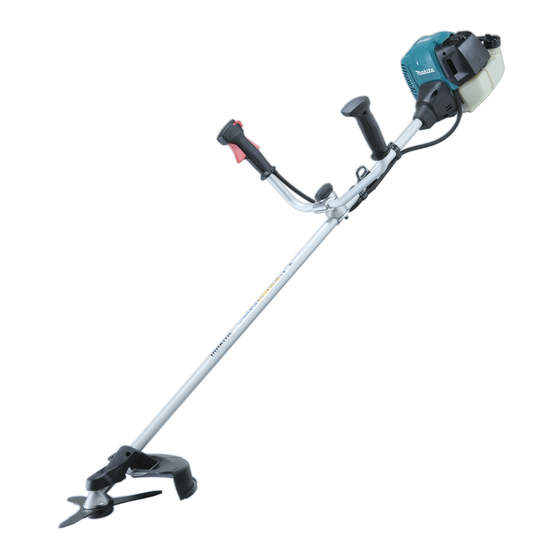
L
The drawing
above is
EM4350UH.
1,812 (71-1/2)
618 (24-1/4)
528 (20-3/4)
Advertisement

Related Manuals for Makita EM4350UH


Summary of Contents for Makita EM4350UH
- Page 1 Socket wrench 16-17, Blade cover ..........1 (for the model with blade) Socket driver 16-10) ....1 Double shoulder straps with waist pad ..1 (for EM4350UH) Accessory bag ..........1 Double shoulder straps with waist pad Oil bottle without oil or for Loop handle model..
-
Page 2: Necessary Repairing Tools
(2) Replace it with a new one. [3] LUBRICANT / ADHESIVE APPLICATION (1) Apply a little amount of Makita grease N No. 2 to Spiral spring in Recoil starter and the spline ends of Shaft in Shaft pipe complete. (2) When the inside of Gear case is cleaned, supply 11g of Makita grease N No. 2 from the grease inlet. - Page 3 (5) For EM4351UH: Remove M5x8 Hex socket head bolt and M6x30 Hex socket head bolt in the holes of Pipe housing. (Fig. 4) For EM4350UH and EM4350LH: Remove M5x8 Hex socket head bolt and M6x30 Hex socket head bolt from the threaded holes of Clutch case. (Fig. 5) (6) Grab Shaft pipe complete by hand, then pull it off from Clutch case.
- Page 4 P / 2 epair [4] DISASSEMBLY/ASSEMBLY [4]-2. Engine and Shaft (cont.) ASSEMBLING Assemble by reversing the disassembly procedure. (1) Put Cable bracket between Flat washer 6 and middle Nut, and tighten them by turning lower nut, upper nut and the middle nut. (Fig. 7) (2) Put Stopper on Inner cable end into Swivel, then adjust the above nuts so that 3mm to 4mm of play is left inside of Swivel under condition that Throttle lever is not pulled.
- Page 5 P / 2 epair [4] DISASSEMBLY/ASSEMBLY [4]-3. Shaft pipe complete (cont.) DISASSEMBLING For 4351UH: (5A) Loosen M5x18 Hex socket head bolt and remove Shaft pipe complete from Pipe housing. (Fig. 11) (6A) Pull out Shaft from Shaft pipe complete. For 4350UH: (5B) Remove two M6x25 Hex socket head bolts and Pipe clamp, then separate Bike handle section from Shaft pipe complete.
- Page 6 P / 2 epair [4] DISASSEMBLY/ASSEMBLY [4]-3. Shaft pipe complete (cont.) ASSEMBLING For 4351UH: (1A) Insert Buffer rubber into Pipe housing so as to align the two grooves with the two ribs (Fig. 16) Set the four Buffer rubbers in place of Fig.
- Page 7 P / 2 epair [4] DISASSEMBLY/ASSEMBLY [4]-4. Gear case assembly DISASSEMBLING (1) According to the clause of [4]-3, Remove Gear case assembly. (Refer to Figs. 8, 9 and 10) (2) Remove M8x10 + Hex bolt from the grease inlet of Gear case assembly. (Fig. 19) (3) Remove Retaining ring R-26 with 1R006.
- Page 8 P / 2 epair [4] DISASSEMBLY/ASSEMBLY Fig. 27 [4]-4. Gear case assembly (cont.) ASSEMBLING 1R028 Assemble by reversing the disassembly procedure. Note: Ball bearing • Make sure that O ring 32 is put into the inner groove of 6000DDU The components of Gear case assembly in advance.
- Page 9 P / 2 epair [4] DISASSEMBLY/ASSEMBLY [4]-6. Clutch drum DISASSEMBLING For 4351UH: Refer to Parts breakdown in Fig. 35. (1A) Remove four M6x20 Hex socket head bolts, then separate Clutch case from Engine. (Fig. 33) (2A) Remove Retaining ring (INT) R-42 in Clutch case with 1R006. (Fig. 33) (3A) Put 1R247 on Clutch drum in Clutch case, press down Clutch drum using Arbor press.
- Page 10 P 1 / 2 epair [4] DISASSEMBLY/ASSEMBLY [4]-6. Clutch drum (cont.) ASSEMBLING For 4351UH: (1) Press-fit Ball bearing 6004LLU to Clutch drum with 1R031 in Fig. 40. Note: Put Retaining ring (INT) R-42 between Ball bearing 6004LLU and Clutch drum in advance. (2) Set Retaining ring (EXT) WR-20 in the groove on Clutch drum.
-
Page 11: Checking Spark Plug
P 1 / 2 epair [4] DISASSEMBLY/ASSEMBLY [4]-8. Ignition system CHECKING PLUG CAP (1) Remove Plug cap from Spark plug, then check the continuity between Plug cap spring and the ground (earth) terminal of Ignition coil with a circuit tester. If there is normal continuity, the resistance value will be 2.0kΩ±0.5kΩ. (Fig. 44) (2) If there is no or intermittent continuity, check the continuity between Ignition cable and Plug cap spring by following the procedure described below. - Page 12 P 1 / 2 epair [4] DISASSEMBLY/ASSEMBLY [4]-7. Ignition system (cont.) Fig. 47 REMOVING IGNITION COIL Female terminal of M4x20 Hex socket Primary wire head bolt (2 pcs.) (1) Before removing Ignition coil, separate Cylinder cover from Engine, and pull out Primary wire from Ignition coil in advance.
- Page 13 Reel first, then by winding Spiral spring counterclockwise towards the center of Reel. (Fig. 54) (2) Apply a little amount of Makita grease N No.2 to the whole surface of Spiral spring. (3) Put a new Starter rope through Starter cover.
- Page 14 P 1 / 2 epair [4] DISASSEMBLY/ASSEMBLY [4]-10. Carburetor section DISASSEMBLING Fig. 58 Fig. 59 (1) Press down the tab of Cleaner plate assembly gently and separate Air cleaner element M5x60 Hex socket head bolt (2 pcs.) Air cleaner cover from Cleaner plate assembly by loosening M5x20 Hex socket button head screw.
- Page 15 epair [4] DISASSEMBLY/ASSEMBLY [4]-10. Carburetor section (cont.) Fig. 66 ASSEMBLING CARBURETOR Assemble by reversing the disassembly procedure. Carburetor Note: Make sure that the assembling direction of each part is correct. VACUUM LEAK TEST OF CARBURETOR 1R127 Connect 1R127 with the fuel inlet of Carburetor, then increase the testing pressure up to 0.05Mpa.
- Page 16 epair [4] DISASSEMBLY/ ASSEMBLY Stop switch section [4]-11. CHECKING STOP SWITCH Fig. 66 Check the continuity between the bullet terminals on the two lead wires extending from Control lever with a circuit tester. (Fig. 66) If Stop switch functions properly, there will be no continuity with the switch ON and there will be continuity with the switch OFF.
- Page 17 epair [4] DISASSEMBLY/ASSEMBLY [4]-13. Engine block DISASSEMBLING (1) It is highly recommended to drain the oil system of Engine block before starting disassembling because the oil remaining there will drip out to delay your operation. (2) From the engine section, remove the following parts): Ignition coil, Flywheel complete, Rocker cover inner, Rocker cover outer, Rocker arm assembly (2 pcs), Rod 2.5 (2 pcs), Cam lifter (2 pcs), Cam gear assembly, Insulator complete, Cleaner plate assembly, Carburetor, Spark plug, Exhaust muffler.
- Page 18 (1) Connect Piston with Crank shaft complete by inserting Piston pin into place; there is no front/back to Piston. Note: Be sure to apply a little amount of Makita grease N No.2 to Needle roller bearing. (2) Secure Piston pin by mounting Clip onto each end of Piston pin. Any setting direction is allowed.
- Page 19 P 19/ 22 epair [4] DISASSEMBLY/ASSEMBLY [4]-13. Engine block (cont.) DISASSEMBLING (8) Adjust Valve clearance as follows: 1. Align the marks on the following parts: Fig. 79 • Ignition coil and Flywheel complete (Fig. 77) • Cam gear assembly and Cylinder block (Fig. 78) 2.
- Page 20 P 20/ 22 epair [4] DISASSEMBLY/ASSEMBLY [4]-13. Engine block (cont.) ASSEMBLING Assemble by reversing the disassembly procedure. [4]-14. Valve section DISASSEMBLING (1) Remove two Rocker arm assemblies and Pin 5 from Cylinder block assembly. (Fig. 85) (2) Push a rag into Cylinder block assembly from the bottom side so as not to fall off Intake valve and Exhaust valve. The rag works as protection of the inside of Cylinder block assembly.
- Page 21 P 21/ 22 epair [4] DISASSEMBLY/ASSEMBLY [4]-14. Valve section (cont.) ASSEMBLING (1) Apply 0.05cc of 4-cycle engine oil to Exhaust valve and Intake valve as drawn in Fig. 88, then insert them into the holes in Cylinder block assembly. (Fig. 89) (2) Push a rag into Cylinder block assembly so as not to fall off Intake valve and Exhaust valve.
- Page 22 Pipe bracket Cleaner plate M6x30 Hex socket head bolt EM4351UH Housing holder Shaft pipe complete M5x18 Hex socket head bolt EM4350UH Pipe clamp Pipe holder M6x25Hex socket head bolt EM4350LH Control lever assembly Shaft pipe complete M5x14 Hex socket head bolt...
Need help?
Do you have a question about the EM4350UH and is the answer not in the manual?
Questions and answers