
Related Manuals for Master Bilt HOAM series


Summary of Contents for Master Bilt HOAM series
-
Page 1: Table Of Contents
INSTALLATION, OPERATION AND MAINTENANCE INSTRUCTIONS HOAM and VOAM Open Air Merchandisers TABLE OF CONTENTS INTRODUCTION STORE CONDITIONS / LOCATION WARNING LABELS AND SAFETY INSTRUCTIONS PRE-INSTALLATION INSTRUCTIONS Inspection for Shipping Damage INSTALLATION INSTRUCTIONS General Instructions Thermometer Installation Shelf and Shelf Lighting Installation Plumbing ELECTRICAL STARTING PROCEDURE... -
Page 2: Introduction
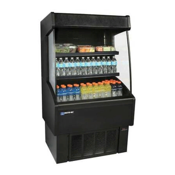
INTRODUCTION Thank you for purchasing this cabinet. This manual contains important instructions for installing, using and servicing an Open Air Merchandiser. Read all these documents carefully before installing or servicing your equipment. This manual should be left in the care of the store owner or manager. STORE CONDITIONS / LOCATION The OAM cases are designed to operate in the controlled environment of an air conditioned store. -
Page 3: Warning Labels And Safety Instructions
WARNING LABELS AND SAFETY INSTRUCTIONS This symbol is the safety-alert symbol. When you see this symbol on your cabinet or in this manual, be alert to the potential for personal injury or damage to your equipment. Be sure you understand all safety messages and always follow recommended precautions and safe operating practices. -
Page 4: Installation Instructions
INSTALLATION INSTRUCTIONS GENERAL INSTRUCTIONS 1. Be sure the equipment is properly installed by competent service people. 2. Keep the equipment clean and sanitary so it will meet your local sanitation codes. Wipe up all spills, clean with water and a mild detergent, then rinse with clean water. A reservoir is provided to contain inner spills. Peridocially inspect reservoir and clean as needed. - Page 5 Shelf Assembly Items 1) If this is a lighted shelf assembly, position shelf brace and cable as shown in the image below. If this is not a lighted shelf assembly, skip this step and proceed to the next step. 2) With shelf top turned upside down, position shelf brace midway inside shelf top and position the shelf brace so the electrical outlet hole is to the left side of the shelf top.
- Page 6 ELECTRICAL OUTLET HOLE 3) Position a shelf bracket with its sides flush with the inside of shelf top and angled as shown in the image below. To fully secure the shelf bracket, the installer needs to pry the angle of the shelf top ,indicated by arrow in the image, so the bracket will snap under shelf top while also manuevering the shelf brace so it fits in the notch of the shelf bracket as the shelf bracket is being lowered into the shelf top.
- Page 7 4) If this is the shelf lighting assembly ,mount lighting assembly in desired location on shelf using magnetic brackets and pull cable as needed to decrease slack in cable. 5) The shelves can be positioned to stock products horizontally or at an angle. To position the shelves horizontally, use the notches indicated on the shelf bracket at the desired level using the spaces available on the pilasters.
- Page 8 6) To position the shelves at a slight angle, use the notches indicated on the shelf bracket at the desired level using the spaces available on the pilasters. Make sure the corresponding pilaster slots are used on both sides to make sure shelves are level. Use the inside notches on shelf bracket to position shelf assemblies at an angle 7) If this is a lighted shelf assembly, plug cable into the nearest outlet located on back panel.
-
Page 9: Plumbing
PLUMBING Each OAM case has an optional electric, heated condensate pan and a looped drain hose connecting the drain to the outside of the case. It is very important that this loop not be removed as it will result in diminished peformance of the case without it. -
Page 10: Electrical
ELECTRICAL WARNING Before servicing electrical components in the case make sure all power to case is off. Always use a qualified technician. STARTING PROCEDURE Start compressor and allow the case to pull down to 42 degrees or below before placing product into the OAM. Check that the compressor cycles off and back on at least once. -
Page 11: Loading
LOADING Product should be at or below operating temperature before being placed in cabinet. Stock cases as quickly as possible, exposing only small quantities to store temperatures for short periods of time. It is important to keep stock rotated properly so that older stock does not accumulate. A “First-In, First-Out” rotation practice will keep the products in good salable condition. -
Page 12: Electronic Temperature Control
ELECTRONIC REFRIGERATION CONTROL Display Lay-out Compressor When power is first turned on to the control, the LED indicator under COMP on the display starts blinking. After one-minute delay the compressor comes on. The LED indicator stays on while compressor relay is energized. -
Page 13: Setpoint
HOW TO CHANGE THE SETPOINT HOW TO CHANGE a parameter value LIST OF PARAMETERS Here is a list of the parameters the value of which can be changed in the programming mode, as well as their ranges. Display Nor-Lake’s Parameter Symbol Range Setting... -
Page 14: Sensor Probe Temperature And Resistance
SENSOR PROBE TEMPERATURE AND RESISTANCE NTC10K Temperature-Resistance Temp (ºC) Temp (ºF) R-low (Kohm) R-center (Kohm) R-high (Kohm) 188.021 195.652 203.573 142.788 148.171 153.741 109.522 113.347 117.294 84.823 87.559 90.374 66.270 68.237 70.255 52.229 53.650 55.104 41.477 42.506 43.557 33.147 33.892 34.651 26.678 27.219... -
Page 15: Service Instructions (Trouble Shooting Guide)
SERVICE INSTRUCTIONS (Trouble Shooting Guide) High head pressure and high back pressure: Condenser coil clogged or restricted. Condenser fan motor defective. Low back pressure and low head pressure: Restriction in system. Refrigerant undercharged. Leak in system. Pressures normal – cabinet warm: Coil blocked with frost or ice. -
Page 16: Part Numbers
REPLACEMENT PART NUMBERS The tables below list replacement part numbers. Use this chart when ordering replacement parts for your VOAM AND/OR HOAM cases. Description VOAM 36-60 VOAM 48-60 VOAM 60-60 VOAM 72-60 Compressor 159267 159268 159269 159269 Condensate Pan 159270 159270 159271 159271... - Page 17 REPLACEMENT PART NUMBERS The tables below list replacement part numbers. Use this chart when ordering replacement parts for your VOAM AND/OR HOAM cases. Description VOAM 36-72 VOAM 48-72 VOAM 60-72 VOAM 72-72 Compressor 159268 159269 159146 159146 Condensate Pan 159271 159271 159147 159147...
- Page 18 REPLACEMENT PART NUMBERS The tables below list replacement part numbers. Use this chart when ordering replacement parts for your VOAM AND/OR HOAM cases. Description VOAM 36-79 VOAM 48-79 VOAM 60-79 VOAM 72-79 Compressor 159268 159269 159146 159146 Condensate Pan 159271 159271 159147 159147...
-
Page 19: Part Numbers
REPLACEMENT PART NUMBERS The tables below list replacement part numbers. Use this chart when ordering replacement parts for your VOAM AND/OR HOAM cases. Description HOAM 36 HOAM 48 HOAM 60 HOAM 72 Compressor 159267 159267 159268 159268 Condensate Pan 159270 159270 159271 159271... -
Page 20: Accessories List
ACCESSORIES LIST Description VOAM 36-60 VOAM 48-60 VOAM 60-60 VOAM 72-60 Shelf Assembly 159133 159134 159135 159136 Shelf Lighting Assembly 159137 159138 153139 159140 Condensate Pump 159141 159141 159141 159141 Casters 2" Diameter 143678 143678 143678 143678 Product Hooks Retractable Night Cover Sandwich Display Hooks Security Cover Description... -
Page 21: Wiring Diagrams
3/15 Rev. C 157872... - Page 22 3/15 Rev. C 157872...
- Page 23 3/15 Rev. C 157872...
- Page 24 3/15 Rev. C 157872...
Need help?
Do you have a question about the HOAM series and is the answer not in the manual?
Questions and answers