Panasonic DP-100 Series Instruction Manual
High-performance digital display pressure sensor
Hide thumbs
Also See for DP-100 Series:
- Quick information manual (28 pages) ,
- Instruction manual (9 pages) ,
- Instruction manual (4 pages)
Advertisement
Quick Links
High-performance Digital Display Pressure Sensor
DP-100 Series
Thank you very much for purchasing Panasonic products. Read this Instruction Manu-
al carefully and thoroughly for the correct and optimum use of this product. Kindly keep
this manual in a convenient place for quick reference.
Never use this product as a sensing device for personnel protection.
In case of using sensing devices for personnel protection, use products which
meet laws and standards, such as OSHA, ANSI or IEC etc., for personnel protec-
tion applicable in each region or country.
This product is designed for use with non-corrosive gas. It cannot be used for liq-
uid or corrosive gas.
A product intended for use in Japan conforms to the Japanese Measurement Act.
Do not use a product intended for use overseas in Japan.
1
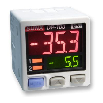
PART DESCRIPTION
Output 1 operation
indicator
Lights up when com-
parative output 1 is ON
Output 2 / analogue
voltage / current out-
put operation indicator
Standard type:
Setting value UP key
Lights up when com-
parative output 2 is ON
Mode selection key
High-function type:
Lights up when analogue
voltage / current output is set
Note: If set the pressure unit other than 'MPa' or 'kPa', attach the unit switching label corresponds to the set pressure
unit.
2
PIPING
When connecting a commercial coupler to the pres-
sure port, attach a 14mm spanner to the pressure
port's hexagon section to fix the port, and then
tighten with a tightening torque of 9.8N·m or less
(M5 female: 1N·m or less). The commercial coupler
or pressure port section will be damaged if the tight-
ening torque is excessive.
Wrap sealing tape around the coupler when con-
necting to prevent leaks.
3
MOUNTING
The sensor mounting bracket MS-DP1-1 is available as an option. When mounting
the sensor onto the sensor mounting bracket, etc., the tightening torque should be
0.5N·m or less.
M3 (length 6mm) screws
with washers
(Accessory with MS-DP1-1)
Sensor mounting bracket
MS-DP1-1 (Optional)
The panel mounting bracket MS-DP1-2 (optional), as well as the front cover
MS-DP1-3 (optional) are also available.
For mounting of the panel mounting bracket, refer to the Instruction Manual en-
closed with MS-DP1-2.
4
WIRING
Make sure to use the cable with connector &1$& when connecting to this
product's connector area.
Tighten the M8 connector completely by hand when mounting. (The tightening
torque: 0.3 to 0.4N·m)
If tightened by a tool such as a plier, it may cause connector damage.
,I WKH WLJKWHQLQJ WRUTXH LV QRW HQRXJK WKH ¿[LQJ ULQJ PD\ ORRVHQ E\ YLEUDWLRQ
Connection method
Insert the cable with connector &1$& (op-
tional) into this product's connector area, and
WZLVW WKH ¿[LQJ ULQJ RI WKH FDEOH ZLWK FRQQHFWRU
WR EH ¿[HG
Disconnection method
Loosen the fixing ring, and, holding the fixing
ring, pull to separate the connector.
Note: Do not pull by holding the cable without pressing the release lever, as this can cause cable break or connector
break.
INSTRUCTION MANUAL
ME-DP110EPJ No.0040-90V
WARNING
Unit display
(Note 1, 2)
Main display
Sub display
Setting value
DOWN key
Pressure port
1
G
/
+ M5 female screw
8
<Connector pin arrangement>
1
2
3
4
5
I/O CIRCUIT DIAGRAMS
When using the analog voltage output, take care to the input impedance of the con-
nected device.
Furthermore, note that if the cable is extended, the cable resistance will cause the
voltage to drop.
Standard type
Connector
High-function type
area
N
1RWHV
:KHQ WKH DQDORJXH FXUUHQW LV RXWSXW WKH RXWSXW ORDG UHVLVWDQFH VKRXOG EH Ÿ PD[
2) Take care that when the analogue current is output, 5V or more voltage generates.
3) When using the analogue voltage output, be careful to the input impedance of the connected device.
Furthermore, note that if the cable is extended, the cable resistance will cause the voltage to drop.
6
OUTPUT MODE AND OUTPUT OPERATION
14mm spanner
The EASY mode, hysteresis mode or window comparator mode can be selected as
the output mode for comparative output 1 and comparative output 2.
Refer to <Comparative output 1 / 2 output mode setting> in "
TING MODE" for details.
EASY mode
ON / OFF of the comparative output is controlled in this mode.
Comparative
ON
output
OFF
1RWHV
+\VWHUHVLV FDQ EH ¿[HG LQ VWHSV
Refer to +\VWHUHVLV ¿[HG YDOXH VHOHFWLRQ! in "
2) "
" is displayed for comparative output 1 and "
Hysteresis mode
The comparative output ON / OFF state can be controlled with randomly set hyster-
esis in this mode.
Hi
Lo
Comparative
ON
output
OFF
Note: "
" or "
sub-display.
Window comparator mode
In this mode, the ON or OFF state of the comparative output is controlled with a
pressure in the set range.
Hi
Lo
M8 connector
&1$&
Comparative
ON
output
OFF
1RWHV
+\VWHUHVLV FDQ EH ¿[HG LQ VWHSV
Refer to +\VWHUHVLV ¿[HG YDOXH VHOHFWLRQ! in "
2) "
" or "
Fixing ring
the sub-display.
6HW WKH LQWHUYDO EHWZHHQ WKH /R VLGH DQG +L VLGH WR K\VWHUHVLV ¿[HG YDOXH RU PRUH
Connector pin No.
Terminal name
1
Standard type: Comparative output 2
2
High-function type: Analogue voltage / current output or external input
3
4
Comparative output 1
(Brown) +V
(Black) Comparative output 1
100mA max.
(White)
Load
Comparative output 2
(Blue) 0V
(Brown) +V
(Black)
Comparative output 1
(White)
Analogue voltage / current output
or external input (Notes 1, 2, 3)
(Blue) 0V
H (Hysteresis)
P
0
9
PRO MODE" for setting.
" for comparative output 2 on the sub-display.
H (Hysteresis)
0
" is displayed for comparative output 1 and "
H (Hysteresis)
H (Hysteresis)
0
9
PRO MODE" for setting.
" is displayed for comparative output 1 and "
+V
0V
100mA max.
+
12 to 24V DC
±10%
-
Load
100mA max.
+
12 to 24V DC
±10%
-
Load
MENU SET-
8
+
+\VWHUHVLV ¿[HG
1RWH
H: 1digit or more
2 digits or more when
using psi unit
" or "
" for comparative output 2 on the
+
+\VWHUHVLV ¿[HG
1RWH
" or "
" for comparative output 2 on
Advertisement

Related Manuals for Panasonic DP-100 Series


Summary of Contents for Panasonic DP-100 Series
- Page 1 DP-100 Series Comparative output 1 ME-DP110EPJ No.0040-90V Thank you very much for purchasing Panasonic products. Read this Instruction Manu- I/O CIRCUIT DIAGRAMS al carefully and thoroughly for the correct and optimum use of this product. Kindly keep this manual in a convenient place for quick reference.
- Page 2 RUN MODE MENU SETTING MODE The mode will change to RUN mode when the mode selection key is held down Setting the threshold value during this setting process. In doing so, changed items before holding down the Refer to <Comparative output 1 / 2 output mode setting>, <Analogue voltage mode selection key have been set.
- Page 3 PRO MODE Code table Main display (1st digit form left) The mode will change to RUN mode when the mode selection key is held down during this setting process. However, changed items before holding down the mode 2nd digit 4th digit 1st digit 3rd digit selection key have been set.
-
Page 4: Specifications
When other error massage is displayed, contact us. http://panasonic.net/id/pidsx/global 2YHUVHDV 6DOHV 'LYLVLRQ +HDG 2I¿FH 2431-1 Ushiyama-cho, Kasugai-shi, Aichi, 486-0901, Japan Phone: +81-568-33-7861 FAX: +81-568-33-8591 About our sale network, please visit our website. PRINTED IN JAPAN © Panasonic Industrial Devices SUNX Co., Ltd. 2013...
Need help?
Do you have a question about the DP-100 Series and is the answer not in the manual?
Questions and answers