Table of Contents
Advertisement
Quick Links
Advertisement
Table of Contents

Related Manuals for Allen-Bradley 839E


Summary of Contents for Allen-Bradley 839E
- Page 1 Solid-State Flow Sensors USER MANUAL 839E...
- Page 2 Important User Information Because of the variety of uses for the products described in this publication, those responsible for the application and use of this control equipment must satisfy themselves that all necessary steps have been taken to assure that each application and use meets all performance and safety requirements, including any applicable laws, regulations, codes and standards.
-
Page 3: Table Of Contents
839E Solid-State Flow Sensors User Manual Table of contents Safety instructions ....... . 2 Designated use. -
Page 4: Safety Instructions
Safety instructions Designated use The Bulletin 839E is a flow switch for measurement and monitoring of mass flow rates in industrial processes. The device has been safely built with state-of-the-art technology and meets the applicable requirements and EC Directives. It can, however, be a source of danger if used incorrectly or for anything other than the designated use. -
Page 5: Product Identification
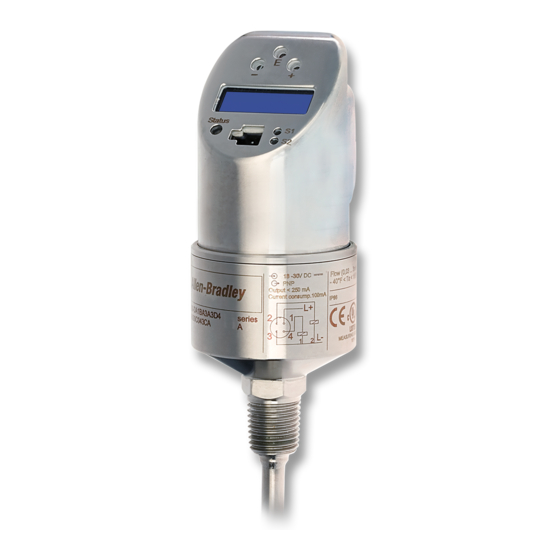
839E Solid-State Flow Sensors User Manual Product identification Flow (0.03…3m/s) –40°F < T < 185°F IP65 839E-DA1BA1A3D4 53009401032 Figure 1 Explanation of the nameplate — see Table below Catalog number Current consumption Series letter Wiring diagram Flow rate and ambient temperature... -
Page 6: Installation
839E Solid-State Flow Sensors User Manual Installation Dimensions M12 x 1 38.7 (1.52) 42.3 (1.66) Dia. 38.5 (1.515) Dia. 24 (0.95) 97.1 (3.82) 42.1 (1.657) 6 (0.24) Dia. 6 (0.24) Dia. Figure 2 Dimensions [mm (in.)] Version L with 30 and 100 mm (1.18 and 3.94 in.) -
Page 7: Process Connection
839E Solid-State Flow Sensors User Manual Process connection The following table illustrates the versions of 839E. 43.5 (1.71) dia. 50.5 (1.99) dia. Measurement and Field of monitoring, mass flow Measuring and monitoring of mass flow rates application rates in sanitary... -
Page 8: Installation Instructions
839E Solid-State Flow Sensors User Manual Installation instructions Figure 3 Installing Bulletin 839E (example). Sensor length L is completely immersed in the flow profile. Mounting instructions: • Any orientation • The on-site display can be rotated electronically 180° — see “Operation” section. - Page 9 839E Solid-State Flow Sensors User Manual Installation instructions Installation conditions Note! The sensor requires a fully developed flow profile for correct monitoring. For this reason, steadying sections (5x DN) must be provided in the pipe after a pump, pipe bend, internal fittings and cross-sectional changes.
-
Page 10: Wiring
• For vertical pipes: installation in the ascending pipeline. • Installation of 839E by min. 3° inclination, because of self draining. Figure 5 Correct orientation • Do not install in down... - Page 11 839E Solid-State Flow Sensors User Manual DC voltage version with M12 connector 4…20 mA Figure 7 DC voltage version with M12 connector Bulletin 839E with M12x1 connector A1: PNP switch outputs R1 and R2 A2: PNP switch output with 4…20 mA analog output Mating cables 2 m (6.5 ft) PVC cable with 4-pin micro...
-
Page 12: Operation
839E Solid-State Flow Sensors User Manual Operation On-site programming The Bulletin 839E is programmed via three push buttons. The digital display and the light emitting diodes (LEDs) assist in the navigation through the operating menu. Operating ke y Digital displa y... - Page 13 839E Solid-State Flow Sensors User Manual Navigating through the programming menu Figure 9 Navigating through the programming menu A Function group selection B Function selection – Enter the programming menu: - Press and hold the E key for longer than 3 sec.
- Page 14 1. Programming buttons [E], [-], and [+] may need to be pressed and held for several seconds before displaying the expected response. 2. When performing a calibration the 839E may require up to 60 seconds to learn the high or low flow rate. The display will indicate “WAIT” during the learn process.
- Page 15 839E Solid-State Flow Sensors User Manual Structure of the operating menu Structure of the operating menu for 1 x analog output (4…20 mA) and 1 x switch output (839E-DCxxxxxx). … Pressing here navigates to Pressing here navigates to To right display (revert to normal) navigate to...
- Page 16 839E Solid-State Flow Sensors User Manual Structure of the operating menu for two switch outputs (839E-DAxxxxxxx) Pressing here navigates to Pressing here navigates to UNIT and inverts the display . To right display (revert to normal) navigate to and press...
- Page 17 839E Solid-State Flow Sensors User Manual Basic settings Function Function group (display) Description BASE Display assignment: (basic functions) Display of current measured value or of configured switch point (switch 1) Display of current measured value or of configured switch point (switch 1) rotated 180°...
- Page 18 839E Solid-State Flow Sensors User Manual Function Function group (display) Description Output switching mode for channel 2: flow or (Setting for the temperature 1st output) Factory setting: flow OUT2 (Setting for Temperature unit selection (°C/°F) the 2nd output, NOTE: Function only visible if switching mode optional) (MODE) is set to temperature in the 2nd output.
- Page 19 839E Solid-State Flow Sensors User Manual Function Function group (display) Description OUT and Can be set anywhere between 0…99 sec. in OUT2 increments of 1 second. (continued) Factory setting: 0 sec. SERV Enter the device locking code. (Service functions) Locking, only visible with valid operating code.
- Page 20 839E Solid-State Flow Sensors User Manual Functions of the switch point • Hysteresis function The hysteresis function enables two-point control via a hysteresis. Depending on the mass flow, the hysteresis can be set via the set point SP and the reset point RSP.
-
Page 21: Programming With Personal Computer And Readwin 2000
839E Solid-State Flow Sensors User Manual Programming with personal computer and ReadWin 2000 The 839E can also be configured via personal computer and ReadWin software. An additional configuration kit with a conversion cable (Part number 836E-NSR) is required to interface the USB port of the PC to the programming port of the flow switch, as shown below. - Page 22 839E Solid-State Flow Sensors User Manual Additional operating options In addition to the operating options listed in the “On-site programming” section, the ReadWin configuration software provides an additional function group with further information on the Bulletin 839E: Function group Function (display)
-
Page 23: Accessories
839E Solid-State Flow Sensors User Manual Accessories Configuration Kit with ReadWin The configuration kit (Catalog Number: 836E-NSR) consists of a software CD and a conversion cable which interfaces the USB port of the PC to the 4-pin programming port on the sensor face. -
Page 24: Troubleshooting
839E Solid-State Flow Sensors User Manual Troubleshooting Error and warning codes If an error occurs in the electronics, the color of the status LED changes from green to red and the background illumination of the digital display changes from white to red. A status LED flashing red and green displays an error or warning code, as outlined below: •... -
Page 25: Repair
The device can be operated, however. Repair Bulletin 839E flow switches are not repairable. Disposal Please pay particular attention to the local disposal regulations of your country. Ensure the materials of the device components are separated and processed accordingly. -
Page 26: Technical Data
839E Solid-State Flow Sensors User Manual Technical data Power supply Supply voltage • DC voltage version 18...30 V DC Current consumption • < 100 mA (open-circuit operation) at 24 V DC, max. 150 mA (open-circuit operation); with reverse polarity protection Power supply failure •... -
Page 27: Operating Conditions
839E Solid-State Flow Sensors User Manual Operating conditions • Any orientation • Top housing section can be rotated 310° Operating conditions: Environment • Ambient temperature range –40…+85 °C (–40…185 °F) • Storage temperature –40…+85 °C (–40…185 °F) • Climate class 4K4H as per DIN EN 60721-3-4 •... - Page 28 839E Solid-State Flow Sensors User Manual Figure 16 p/T load diagram L = insertion length vW = water fluid velocity = 3 m/s (9.84 ft/s) Flow Switch Conversion Feet per second (ft/s) to gallons per minute (gpm) Conversion ft/s to gpm 1000.0...
- Page 29 839E Solid-State Flow Sensors User Manual Pub #10000004735 Ver 03, May 2012...
- Page 30 839E Solid-State Flow Sensors User Manual Pub #10000004735 Ver 03, May 2012...
- Page 31 839E Solid-State Flow Sensors User Manual Pub #10000004735 Ver 03, May 2012...
- Page 32 Publication 10000004735 Ver 03 — May 2012 © 2012 Rockwell Automation. Printed in the U.S.A.
Need help?
Do you have a question about the 839E and is the answer not in the manual?
Questions and answers