Table of Contents
Advertisement
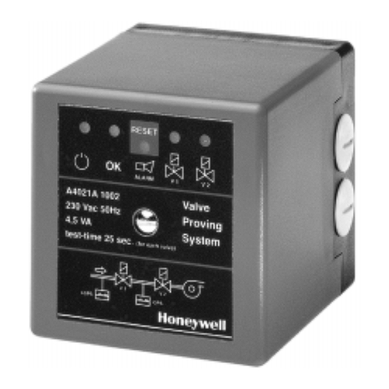
UNIVERSAL GAS VALVES
A4021 Series
VALVE PROVING SYSTEM
PRODUCT HANDBOOK
APPLICATION
The A4021 is a self--checking microprocessor based Valve
Proving System (VPS). The A4021 checks the effective clo-
sure of automatic shut--off valves by measuring the pressure
differential between two valves during the test sequence.
Subbase and pressure switch are required to complete the
system.
When during the test sequence of the A4021 a failing valve is
detected, the A4021 will go into a non--volatile lock--out sta-
tus, generates an alarm and prevents a burner start--up.
The intended application is for gas fired power burners and
other large capacity gas firing installations, where according
to the European norm EN676 a valve proving system can be
used as an alternative for pre--purging the combustion cham-
ber. And for installations with or without pre--purge with a
capacity of more than 1200 kW.
EN2R--9023 9705R0--NE
Advertisement
Table of Contents


Need help?
Do you have a question about the A4021 Series and is the answer not in the manual?
Questions and answers