
Related Manuals for BEKA Advisor A90-SS


Summary of Contents for BEKA Advisor A90-SS
- Page 1 Advisor A90-SS Rugged universal process panel meter with multicolour display Issue 2 Issue: 2 13th April 2017...
-
Page 2: Table Of Contents
2 2 2 2 2 2 2 2 2 2 2 CONTENTS Description 6. Maintenance 6.1 Fault finding during commissioning 6.2 Fault finding after commissioning Operation 6.3 Servicing 2.1 Controls 6.4 Routine maintenance 6.5 Guarantee 6.6 Customer comments Applications 3.1 Power supply 7. -
Page 3: Description
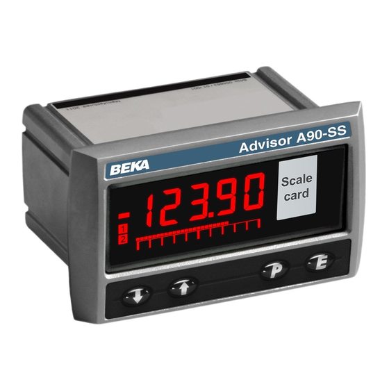
1. DESCRIPTION 2. OPERATION The Advisor A90-SS Rugged Universal Panel Fig 1 shows a simplified block diagram of the Meter is a multicolour five digit instrument, A90-SS Process Panel Meter. Field wiring primarily intended for displaying a current, voltage terminals are the same for... - Page 4 2.1 Controls Unused unless tare function tare is The Advisor A90-SS panel meter is controlled and enabled. When tare function is calibrated via the four front panel push buttons enabled operating this button for less located below the display. In the display mode i.e.
- Page 5 3. APPLICATIONS 3.1 Power supply 3.1.1 Mains powered version The mains powered version of the A90-SS panel mounting meter will operate from a wide range of voltage and frequency ac supplies. Voltage 90 to 264V rms ac Frequency 47 to 63Hz Power 2.5W Fig 2 A90-SS Process panel meter measuring...
- Page 6 Fig 4 shows the connections for two and three wire resistance thermometers Fig 5 connections for differential measurements. Fig 4 Connections for a 2 or 3 wire resistance thermometer. Fig 5 Connections for differential resistance thermometer measurements.
-
Page 7: Installation
4. INSTALLATION Fig 6 show the overall dimensions of the indicators together with the recommended panel enclosure cut-out dimensions. 4.1 Location The A90-SS panel meter has a rugged stainless steel case with a 10mm thick toughened glass window. The case provides 7J and the window 4J front of panel impact protection. -
Page 8: Installation Procedure
If the enclosure panel is less than 1.0mm New meters are supplied with a printed scale card thick, or is non-metallic, an optional BEKA showing the requested units of measurement. If stainless steel support plate should be slid... -
Page 9: Configuration And Calibration
5. CONFIGURATION AND CALIBRATION All new meters are supplied configured and The A90-SS process panel meter is configured and calibrated as requested at the time of ordering. If calibrated via the four front panel push buttons. All calibration is not requested, meters will be the configuration functions are contained in an configured as follows: easy to use intuitive menu that is shown... - Page 10 Security Code Enter code by pressing Display Display * or & and ( DISPLAY mode mode to move to next digit. Code 0000 allows direct access to the menu Only appears Only appears Only appears when Only appears when Only appears when when current when RTD voltage or current...
- Page 11 Only appears when voltage When fitted optional or current 4/20mA current output When fitted optional alarm inputs are appears here functions appear here selected holds U--PSs U--PSs colorSs 5elSs editSs r5etSs 1 . Lrgbs p5et. 1 s Select type of bargraph display and define Function of P Tare Function Hold Function...
-
Page 12: Summary Of Configuration Functions
5.1 Summary of configuration functions Display Summary of function This section summarises each of the main configuration functions and includes a cross Calibration of the digital display using reference to a more detailed description. Fig 9 an external source only for current or illustrates the location of each function within the voltage inputs. - Page 13 Display Summary of function Display Summary of function Maximum and minimum hold function Set meter display colour hold color When enabled, the A90-SS meter will Contains three sub-functions which store maximum minimum enable the colour of the meter display readings which can then be accessed to be selected.
- Page 14 5.2 Input type: input 5.4 Units of temperature: deg This configuration function defines the A90-SS This configuration function only appears in menu panel meter’s input type and range. One of eight when the A90-SS panel meter is configured for a inputs may be selected.
- Page 15 The position of the displayed decimal point does Notes: not affect the position of the decimal point in any of a. The A90-SS meter input current or voltage must the other configuration menus. Therefore when be adjusted to the required value before the adjusting the CAL, 5et or bar functions, 2ero and 5pan functions are entered by decimal point position within the function should...
- Page 16 To adjust the display at the span input, press the The sub-function clr. t removes any zero and span trim that has been applied and returns the A90-SS button which will cause the meter to display meter’s temperature display calibration to the 5PAn pressing will then reveal the meter’s Pt100 figures specified in IEC 60751.
-
Page 17: Tare Function: Tare
When both are set as required, pressing ) twice 5.13 Maximum and minimum hold function: hold will return the display to the bAr prompt in the When enabled, the panel meter will store the configuration menu. maximum and minimum display readings since the maximum and minimum stores were last reset Note: bArLo must be set lower than bArHi, &... -
Page 18: Security Code: Code
5 . lrgb returned to the display mode. Please contact BEKA associates sales department if the security with the preset number flashing. code is lost. The preset colour to be adjusted can be selected using the &... -
Page 19: Fault Finding During Commissioning
Isolate supply to We recommend that faulty instruments are alarm contacts before starting maintenance. returned to BEKA associates or to your local BEKA agent for repair. 6.1 Fault finding during commissioning If a meter fails to function during commissioning 6.4 Routine maintenance... -
Page 20: Scale Card
7. ACCESSORIES 7.3 Alarms CAUTION 7.1 Scale card These alarm outputs should not be used for The A90-SS panel meter has a window on the right critical safety applications such hand side of the display through which to view a emergency shut down system. -
Page 22: Configuration And Adjustment
Display Summary of function Alarm function Hi. Lo Defines the alarm function as High or Low. See section 7.3.5 Alarm relay energised nd . nE de-energised in non alarm condition. Determines whether the alarm relay is energised de-energised non alarm condition. See section 7.3.6 Hysteresis H5tr... -
Page 23: Alarm Enable: Enbl
7.3.3 Alarm enable: EnbL 7.3.7 Hysteresis: H5tr This function allows each alarm to be enabled or Hysteresis is shown in the units that the meter has disabled without altering any of the alarm been calibrated to display. parameters. To enable or disable the alarm select To adjust the hysteresis select H5tr from the alarm EnbL from the alarm menu and press ( which will menu and press... -
Page 24: Alarm Silence Time: 5Il
7.3.9 Alarm silence time: 5iL 7.3.11 Latch alarm output: Latch This function is primarily intended for use in small For some applications it is desirable to retain the installations where the alarm output directly A90-SS meter alarm output after the alarm operates an alarm annunciator such as a sounder condition no longer exists. -
Page 25: Adjusting Alarm Setpoint From The Display Mode
To check or change this function select AC5P from the main meter configuration menu and press which will display the function enable prompt EnbL. Pressing again will reveal if the direct access & menu is on or oFF. The button will then toggle the display between the two conditions. -
Page 26: Display Setpoints On The Bargraph
7.3.15 Displaying setpoints on the bargraph 7.4 4/20mA output and transmitter supply One of the selectable bargraph formats Alr5P The A90-SS panel meter can be supplied with a factory fitted isolated 4/20mA current sink and a allows a low or a high setpoint plus the displayed value to be represented, or a low and a high galvanically isolated 24V dc supply as shown in setpoint plus the displayed value to be represented... -
Page 27: System Design For Powering A
7.4.2 System design for powering a transmitter 7.4.3 Configuration and calibration The 24V dc power supply is galvanically isolated When an A90-SS meter is supplied with an and may be used to power a 2-wire 4/20mA optional 4/20mA output the configuration menu is remote transmitter and to display its output in extended as shown in Fig 18 engineering units as shown in Fig 17... -
Page 28: 4/20Ma Enable: Enbl
7.4.4 4/20mA enable: EnbL 7.4.7 RTD fault detection: fault This function allows the 4/20mA output to be Fault function is only included in the 4/20mA enabled or disabled without altering its calibration. configuration menu when the A90-SS meter is To enable or disable the 4/20mA output select configured for a Resistance Thermometer input.
Need help?
Do you have a question about the Advisor A90-SS and is the answer not in the manual?
Questions and answers