Table of Contents
Advertisement
1601 J. P . Hennessy Drive, LaVergne, TN USA 37086-3565 615/641-7533 800/688-6359
HENNESSY INDUSTRIES INC. Manufacturer of AMMCO
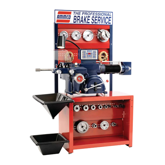
4000E
Drum & Disc
Brake Lathe
®
Installation Instructions
Operating Instructions
Safety Instructions
Maintenance Instructions
READ these instructions before placing unit in
service. KEEP these and other materials delivered
with the unit in a binder near the machine for
ease of reference by supervisors and operators.
®
, COATS
®
and BADA
®
Automotive Service Equipment and Tools.
* Brake lathe shown on
bench with sign, toolboard
and accessories.
Manual Part No.: 95000103 00
Revision:
02/08
Advertisement
Table of Contents

Related Manuals for AMMCO 4000E


Summary of Contents for AMMCO 4000E
- Page 1 1601 J. P . Hennessy Drive, LaVergne, TN USA 37086-3565 615/641-7533 800/688-6359 Manual Part No.: 95000103 00 HENNESSY INDUSTRIES INC. Manufacturer of AMMCO ® , COATS ®...
- Page 2 OFF (O) position before plugging the machine in or is necessary, do not connect the equipment-grounding con- performing any maintenance or service work. ductor to a live terminal. SAVE THESE INSTRUCTIONS ii • AMMCO Drum & Disc Brake Lathes...
-
Page 3: Table Of Contents
Connect to Power ......17 Operating Specifications ....17 AMMCO Drum & Disc Brake Lathes • 1... -
Page 4: Owner's Responsibility
Your safety, or the safety of others, is involved! ible. • If ownership of the unit is transferred, provide new owner all information, manuals, and provide AMMCO new ownership information. 2 • AMMCO Drum & Disc Brake Lathes... -
Page 5: Safety Notices And Decals
4. Keep bystanders out of work area. 5. Unplug unit from power source before servicing or adjusting. 6. Maintain unit properly, keep work surfaces and work area clean. AMMCO Drum & Disc Brake Lathes • 3... -
Page 6: Principle Operating Parts
Cross Feed Handwheel Drum Start/Stop – press to start or stop feed. Feed Lever Cross Feed Lock Cross Feed Lock Knob Spindle Speed Adjusting Lever Power Cord ON/OFF Switch Boring Bar and Boring Clamp 4 • AMMCO Drum & Disc Brake Lathes... - Page 7 Top View Front View Not Shown ✓ Do It Now! Now is a good time to fill out the Owner’s Registry Card. AMMCO Drum & Disc Brake Lathes • 5...
-
Page 8: Basic Operation
Note: These are only suggested speed and feed ranges. Adjust settings as needed to find the optimum setting for your application. Workpiece 6 to 9 8 to 15 15 & Up Diameter (inches) Spindle RPM Rough Feed Finish Feed 6 • AMMCO Drum & Disc Brake Lathes... -
Page 9: Cross Feed Handwheel & Feed Lever
Handtighten the nut only at this point. Make sure the tool bit is clean and sharp. Replace as necessary to ensure smooth reconditioning. Boring Bar Clamp Figure 2 - Boring Bar AMMCO Drum & Disc Brake Lathes • 7... -
Page 10: Reconditioning Disc Brake Rotors
Note: Most often the DISCARD thickness dimension is cast or stamped into the rotor, not the minimum machine-to thickness. 8 • AMMCO Drum & Disc Brake Lathes... -
Page 11: Rotor Mounting
- Self-Aligning Spacer - Spacer - Spring - Small Hubless Adapter - Large Hubless Adapter - Centering Cone - Small Double Taper Adapter - Large Double Taper Adapter - Adapter, Used as Spacer AMMCO Drum & Disc Brake Lathes • 9... -
Page 12: Double Chuck Adapter
Double Chuck Adapter Set Up and Reconditioning Rotors Mounting drums or rotors using the Ammco double 1. Install a silencer band on the mounted rotor. chuck adapter. Stretch the band around the rotor and hook the metal loop over a lead weight. - Page 13 5. Make sure that the tool bits clear the rotor sur- faces and the silencer band. Give the rotor a full turn by hand and watch for clearance all the way around. AMMCO Drum & Disc Brake Lathes • 11...
- Page 14 A dial indicator may be used to compare rotor runout with manufacturer’s specifications. Dial indicator Scratch cuts opposite each other Figure 15 – Using a dial indicator 12 • AMMCO Drum & Disc Brake Lathes...
-
Page 15: Reconditioning Brake Drums
DO NOT overtighten the arbor nut. Figure 18 - Mounting the Drum Note: Also refer to the Double Chuck Adapter section (page 10) when mounting drums or rotors using the Ammco ® double chuck. AMMCO Drum & Disc Brake Lathes • 13... - Page 16 Tighten the lock screw. 14 • AMMCO Drum & Disc Brake Lathes...
- Page 17 20. At the control console, select to activate either the drum rough cut or drum finish cut button. The drum feed rate may be changed by pressing either + or - but- ton on the control console. AMMCO Drum & Disc Brake Lathes • 15...
-
Page 18: Maintenance And Service
Do not throw them into a box. The adapters are designed for mounting drums and rotors only. Do not misuse the adapters. Relief slot Figure 27 – Cross feed grease fitting 16 • AMMCO Drum & Disc Brake Lathes... -
Page 19: Installation Instructions
1" Arbor ....200 lbs [45.36 kg] 1.875" Arbor ... .200 lbs [90.72 kg] AMMCO Drum & Disc Brake Lathes • 17... - Page 20 95000103 00 02/08 © Copyright 2007 Hennessy Industries and AMMCO All Rights Reserved Printed in USA...
Need help?
Do you have a question about the 4000E and is the answer not in the manual?
Questions and answers