Table of Contents
Advertisement
1601 J. P . Hennessy Drive, LaVergne, TN USA 37086-3565 615/641-7533 800/688-6359
HENNESSY INDUSTRIES INC. Manufacturer of AMMCO
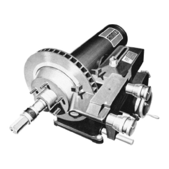
7000
Disc Rotor Lathe
®
Installation Instructions
Operating Instructions
Safety Instructions
Maintenance Instructions
READ these instructions before placing unit in
service. KEEP these and other materials delivered
with the unit in a binder near the machine for
ease of reference by supervisors and operators.
®
, COATS
®
and BADA
®
Automotive Service Equipment and Tools.
Manual Part No.:
910369 02
Revision:
06/01
Advertisement
Table of Contents

Subscribe to Our Youtube Channel
Related Manuals for AMMCO 7000


Summary of Contents for AMMCO 7000
- Page 1 1601 J. P . Hennessy Drive, LaVergne, TN USA 37086-3565 615/641-7533 800/688-6359 Manual Part No.: 910369 02 HENNESSY INDUSTRIES INC. Manufacturer of AMMCO ® , COATS ® and BADA ®...
- Page 2 Brake Lathes ii • AMMCO 7000 Brake Lathes...
-
Page 3: Table Of Contents
Cleaning ......12 Care of Arbors and Adapters ....13 AMMCO 7000 Brake Lathes • iii... -
Page 4: Safety Notices And Decals
For additional copies of either, or further information, contact: Hennessy Industries, Inc. 1601 J.P . Hennessy Drive LaVergne, TN 37086-3565 (615) 641-7533 or (800) 688-6359 www.Hennessy-Ind.com iv • AMMCO 7000 Brake Lathes... -
Page 5: Owner's Responsibility
3. Keep all guards, shields, and covers in place and in working order. 4. Keep bystanders out of work area. 5. Unplug unit from power source before servicing or adjusting. 6. Maintain unit properly, keep work surfaces and work area clean. AMMCO 7000 Brake Lathes • v... -
Page 6: Important Safety Instructions
Safety glasses, goggles, or a face shield contact persons in the area causing personal injury. will help protect the operator from injury. Use a face shield and dust mask during dusty operations. SAVE THESE INSTRUCTIONS vi • AMMCO 7000 Brake Lathes... -
Page 7: Installation
Replace or repair damaged or worn cords immediately soon as it is received. The signed bill of lading is AMMCO electrical and electronic based machines are acknowledgement by the carrier of receipt in good con- designed for nominal line voltages with variations of dition of shipment covered by our invoice. -
Page 8: Lathe Operation
115 VAC, 60 Hz, I Ph, 14 amp - standard 220 VAC, 60 Hz, I Ph, 7 amp - optional (Unless Otherwise Specified) Floor Space Requirements 48 in. wide x 34-3/4 in. deep (When Mounted On Optional Bench) (1219.20 mm x 882.65 mm) 2 • AMMCO 7000 Brake Lathes... -
Page 9: Lathe Components
Brake Lathes Lathe Components AMMCO 7000 Brake Lathes • 3... -
Page 10: Arbor Installation
Spindle Speed - Release the belt tension by moving the V-belt adjusting lever clockwise, Fig. B 3. Move the belt to the pulley groove that will give the correct spindle speed for the cut to be taken, Fig. B 4. Figure B4 4 • AMMCO 7000 Brake Lathes... - Page 11 7. Turn the outer knurl of the twin cutter control left and right to check for a smooth, free movement. Repeat the procedure for the other tool-bit holder. AMMCO 7000 Brake Lathes • 5...
-
Page 12: Reconditioning Disc Brake Rotors
The patented self-aligning spacer prevents diagonal thrust on the adapters. The self-aligning spacer should always be used adjacent to the arbor nut. 6 • AMMCO 7000 Brake Lathes... -
Page 13: Reconditioning Disc Brake Rotors-Set-Up
Fig. B 11. Also always wear safety glasses or a face shield. Cutting or grinding on an exposed sur- face such as a rotor will produce flying chips. Figure B11 Figure B10 AMMCO 7000 Brake Lathes • 7... - Page 14 Turn the left hand tool bit control until the tool bit contacts the rotor surface and makes a scratch cut no deeper than .001", Fig. B 14. Figure B13 Figure B14 8 • AMMCO 7000 Brake Lathes...
- Page 15 Examine each adapter and the arbor for nicks, burrs, chips, dirt, and rust. Also inspect the rotor hub for loose or damaged bearing cups. Clean, repair, remount, or replace as necessary. Figure B16 Figure B17 AMMCO 7000 Brake Lathes • 9...
-
Page 16: Machining
10. Now engage the automatic cross feed (by moving the knob), Fig. 19. When the cross feed has moved the cutting tools all the way across the face of the rotor, the feed will shut off automatically. Figure B19 10 • AMMCO 7000 Brake Lathes... -
Page 17: Typical Rotor Mounting Configurations
Adapter Being Used As Spacer B Arbor Nut F Aligning Cup J Tapered Cone Adapter C Self-Aligning Spacer G Centering Cone K Spacer D Spring H Tapered Cone Adapter L Small Diameter Hubless Adapter AMMCO 7000 Brake Lathes • 11... -
Page 18: Maintenance And Service
DO NOT USE COMPRESSED AIR TO BLOW THE LATHE CLEAN. Chips and dust could be driven between machined parts and into bearings causing undue wear. Figure C2 Figure C3 12 • AMMCO 7000 Brake Lathes... -
Page 19: Care Of Arbors And Adapters
Handle the adapters and arbors with care and store them on individual hooks. DO NOT throw them into a box. The adapters are designed for mounting rotors only, DO NOT misuse the adapters. AMMCO 7000 Brake Lathes • 13... - Page 20 910369 02 06/01 © Copyright 1989 Hennessy Industries and AMMCO All Rights Reserved Printed in USA...
Need help?
Do you have a question about the 7000 and is the answer not in the manual?
Questions and answers