Table of Contents
Advertisement
1601 J. P . Hennessy Drive, LaVergne, TN USA 37086-3565 615/641-7533 800/688-6359
HENNESSY INDUSTRIES INC. Manufacturer of AMMCO
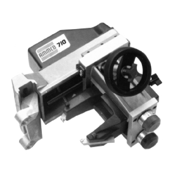
700/705/710
Vehicle Mounted
Brake Lathe &
Rotor Driving Unit
®
Installation Instructions
Operating Instructions
Safety Instructions
Maintenance Instructions
READ these instructions before placing unit in
service. KEEP these and other materials delivered
with the unit in a binder near the machine for
ease of reference by supervisors and operators.
®
, COATS
®
and BADA
®
Automotive Service Equipment and Tools.
Manual Part No.:
927588 16
Revision:
06/01
Advertisement
Table of Contents


Need help?
Do you have a question about the 700 and is the answer not in the manual?
Questions and answers