Riello Burners Gulliver RG1RKD Installation, Use And Maintenance Instructions
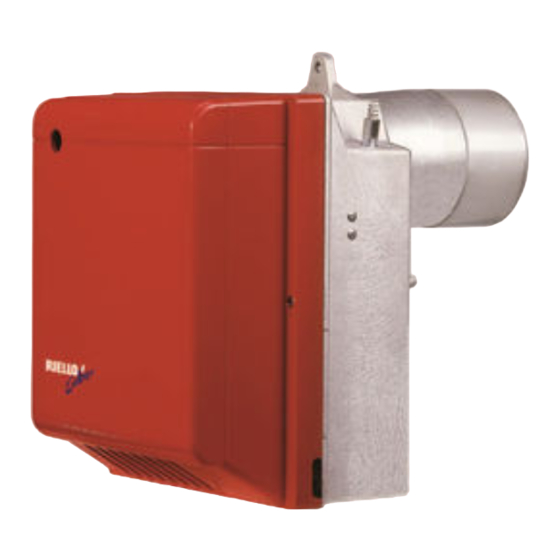
Oil burner
Hide thumbs
Also See for Gulliver RG1RKD:
- Installation, use and maintenance instructions (44 pages) ,
- Installation, use and maintenance instructions (44 pages)
Table of Contents
Advertisement
Quick Links
Montage und Bedienungsanleitung
Manuel d'entretien
Installation, use and maintenance instructions
Installatie-, gebruiks- en onderhoudsvoorschriften
Öl-Gebläsebrenner
D
Brûleur fioul
F
Oil burner
GB
Stookoliebrander
NL
Zweistufiger Betrieb
Fonctionnement à 2 allures
Two stage operation
Tweetrapsbranders
CODE
3736650
MODELL - MODELE - MODEL
RG1RKD
TYP - TYPE
366 T1
2902305 (5)
Advertisement
Table of Contents

Subscribe to Our Youtube Channel
Related Manuals for Riello Burners Gulliver RG1RKD


Summary of Contents for Riello Burners Gulliver RG1RKD
- Page 1 Montage und Bedienungsanleitung Manuel d’entretien Installation, use and maintenance instructions Installatie-, gebruiks- en onderhoudsvoorschriften Öl-Gebläsebrenner Brûleur fioul Oil burner Stookoliebrander Zweistufiger Betrieb Fonctionnement à 2 allures Two stage operation Tweetrapsbranders CODE MODELL - MODELE - MODEL TYP - TYPE 3736650 RG1RKD 366 T1 2902305 (5)
-
Page 2: Table Of Contents
INDEX BURNER DESCRIPTION ... . WORKING ..... . . 1.1 Burner equipment ....4.1 Combustion adjustment. -
Page 3: Technical Data
TECHNICAL DATA 2.1 TECHNICAL DATA TYPE 366 T1 – – Output - Thermal power 1.2 / 1.45 5 kg/h 14 / 17 60 kW Fuel Light oil, viscosity 4 – 6 mm /s at 20 °C ± Electrical supply Single phase, 230 V 50Hz Motor Run current 0.85 A –... -
Page 4: Installation
INSTALLATION 3.1 BOILER FIXING Fig. 2 Fig. 4 D5012 Fig. 3 S7189 Put on the flange (1) the screw and two nuts, (see fig. 3). Widen, if necessary, the insulating gasket holes (5), (see fig. 4). Fix the flange (1) to the boiler door (4) using screws (2) and (if necessary) the nuts (3) interposing the insulating gasket (5) , (see fig. -
Page 5: Hydraulic Systems
3.3 HYDRAULIC SYSTEMS WARNING: Before starting the burner make sure that the return pipe-line is not clogged. An excessive back pressure would cause the damage of the pump seal. The pump is designed to allow working with two pipes. In order to obtain one pipe working it is necessary to unscrew the return plug (2), remove the by-pass screw (3) and then screw again the plug (2), (see fig. -
Page 6: Electrical Wiring
3.4 ELECTRICAL WIRING NOTES: WARNING – Wires of 1 mm 2 section . DO NOT EXCHANGE – The electrical wiring carried out by the installer must be in NEUTRAL WITH PHASE compliance with the rules in force in the Country. Connect 2nd stage thermostat between clamps T6 - T8 by removing the bridge. -
Page 7: Working
WORKING 4.1 COMBUSTION ADJUSTMENT In conformity with Efficiency Directive 92/42/EEC the application of the burner on the boiler, adjustment and testing must be carried out observing the instruction manual of the boiler, including verification of the CO and CO concentration in the flue gases, their temperatures and the average temperature of the water in the boiler. To suit the required appliance output, choose the proper nozzle and adjust the pump pressure, the setting of the combustion head, and the air damper opening in accordance with the following schedule. -
Page 8: Electrodes Adjustment
Fig. 12 – Remove nozzle-holder assem- bly (1) after loosing screws (2) and nut (3), re- move the small cables (4) from the control box, the photoresistance (5) and the socket (6). – Withdraw the small cables (4) from the elec- trodes, remove the diffuser disc-holder assem- bly (9) from the nozzle-holder assembly (1) after loosing screw (3, fig. -
Page 9: Pump Pressure And Air Output
4.3 PUMP PRESSURE AND AIR OUTPUT STAGE ADJUSTMENT ADJUSTMENT OF AIR SHUTTER: Unloosen the nut (1), turn the screw (2) until the indicator (3) reaches the position desired. Then lock the nut (1), (see fig. 14). PRESSURE REGULATION: This is set at 9 bar at the factory. Should it be necessary to re-set or alter such pressure, this can be done, by adjusting screw (7). -
Page 10: Fuel Heating
4.4 FUEL HEATING In order to assure regular ignition and working also at low temperature the burner has an oil pre-heater fitted in combustion head. The pre-heater starts when thermostats close. When the required temperature for ignition is reached the thermostat fitted on the nozzle holder starts the burner. -
Page 11: Boiler Fixing
FAULTS / SOLUTIONS Here below you can find some causes and the possible solutions for problems that could cause a failure to start or a bad working of the burner. A fault usually makes the lock-out lamp light which is situated inside the reset button of the control box (4, fig.
Need help?
Do you have a question about the Gulliver RG1RKD and is the answer not in the manual?
Questions and answers