
Related Manuals for S.R.Smith MultiLift


Summary of Contents for S.R.Smith MultiLift
- Page 1 Owner’s Manual and Maintenance Procedures 1017 SW Berg Parkway Canby, OR 97013 Phone: 503.266.2231 Toll Free: 800.824.4387 www.srsmith.com 700-9000 6.14.13...
-
Page 2: Table Of Contents
APPENDIX A: multiLift™ ASSEMBLY ................22 APPENDIX B: multiLift™ EXPLODED View ..............23 APPENDIX C: multiLift™ CHAIR ................25 APPENDIX D: multiLift™ Chair Right to Left Conversion ..........26 APPENDIX E: New Construction Jig ................30 700-9000... -
Page 3: Deck Profile Sheet Confirmation
Aquatic access lifts are application specific. A completed Deck Profile Sheet helps to ensure the lift purchased for the application will work in accordance to ADA guidelines. S.R. Smith reviews all submitted Deck Profile Sheets as a service to our customers, free of charge. Before installing the pool lift, the installer must review and confirm the information provided on the Deck Profile Sheet. -
Page 4: Introduction And Summary
User. If the multiLift™ will be used by a disabled person living on their own, a communication device should be installed in the area of use to call for assistance in the event of an emergency. - Page 5 WARNINGS AND SAFETY SUMMARY DANGER – FAILURE TO FOLLOW THESE WARNINGS, INSTRUCTIONS AND THE OWNER’S MANUAL MAY RESULT IN SEROUS INJURY OR DEATH ADA GUIDELINE SUMMARY* (USA Only) 1009.2.1 Pool Lift Location Pool lift shall be located where the water level does not exceed 48”. If entire pool water level exceeds 48”, place pool lift where convenient.
-
Page 6: Product Overview
This ensures consistent safe operation and minimizes service problems. The multiLift™ has a mast height of 42 in / 106.6 cm above the deck. It is intended to be used with simple pool gutter configurations having a deck to water distance of no more than 8 inches, see Table 1 and Figure 10 to determine if the multiLift™... -
Page 7: Component Description
Plastic Protective Pad- The protective plastic pad is designed to be attached to the bottom side of the multiLift™ mounting plate and act as a protective barrier to prevent damage to the multiLift™ base plate or the pool deck. -
Page 8: Unpacking & Assembly Instructions
It is recommended that the anchor be installed by a person familiar with installing pool deck equipment. The multiLift™ is shipped on a covered pallet and is mostly assembled. Position crate close to deck anchors for easier assembly and set up. - Page 9 8. The LiftOperator Control is pre-assembled on the multiLift™ (see LiftOperator Owner’s Manual for more information). Remove the hand control from accessory carton and unwrap. Insert plug into large socket on the LiftOperator control box as shown in Figure 4. Make sure plug is secure.
-
Page 10: Using The Multilift
User. If the multiLift™ will be used by a disabled person living on their own, a communication device should be installed in the area of use to call for assistance in the event of an emergency. -
Page 11: Transferring The User To The Water
Once the unit is positioned for use, use the following procedure to transfer to the seat and into the water. Only persons healthy enough for water activities should use the multiLift™. Users should consult with their physician to determine if water activities are appropriate for the User: ... -
Page 12: Pool Deck Installation For The Multilift
The setback distance from the pool edge to the front anchor locations varies depending upon pool geometry. The multiLift™ is designed to be used with simple pool edge designs with deck to water level differences of 0” to 8”... -
Page 13: Installing Anchors Into Existing Concrete Deck
3. Use Figure 10 and Table 1 to determine the proper location to install the lift, making certain that the front anchors are located the correct distance from the pool edge. 4. Layout and mark the hole locations on the deck using the multiLift™ Anchor Set Jig as a template. - Page 14 Figure 13. Deck Anchor Installation 8. The multiLift™ Anchor Jig must be used to ensure that the anchors are held in the correct position until the epoxy is cured. To use the Anchor Jig, place the ½”-13 X 2” Hex Bolts through the tubes in the Anchor Jig and thread the bolts into the anchors until the top surface of the anchors contact the bottom of the Anchor Jig tubes.
-
Page 15: Installing Anchor Jig Into New Concrete Deck
Figure 14. Deck Anchor Bonding INSTALLING ANCHOR JIG INTO NEW CONCRETE DECK Figure 15. Deck Anchor Jig Installation 700-9000 6.14.13... -
Page 16: Standard Accessories/Optional Accessories
Wheel-A-Way transport wheels (optional). The Wheel- A-Way transport wheels are designed to facilitate moving the multiLift™ from one anchor location to another, or to a storage area. See Appendix F for details. -
Page 17: Maintenance And Cleaning
MAINTENANCE and CLEANING A maintenance program will prolong the life of your lift. Keep all electronic components clean and dry. Keep the console/battery cover installed at all times to prevent moisture from collecting on the control box and battery. Excessive moisture collection can affect battery and lift performance and could lead to battery failure and/or the lift failing to operate. -
Page 18: Long-Term Storage
If none of the above steps work in getting the lift to function, call S.R. Smith for assistance. LONG-TERM STORAGE When storing the lift for an extended period of time: ... -
Page 19: Warranty Information
WetDek™ (1 year) and PoolSonix™ (2 years). The original retail purchaser must follow the procedure set forth below when submitting a warranty claim. S.R. Smith will repair or replace, at its option, the product, and return it to the owner freight prepaid. - Page 20 No representative of S.R. Smith, nor any of its agents, distributors or dealers has any authority to alter in any manner the terms of this warranty and S.R. Smith is not responsible for any undertaking, representation or warranty made by any other person beyond the warranty expressly set forth in this warranty.
-
Page 21: Specifications
BATTERY DISPOSAL The battery is recyclable and shall be disposed of in accordance with applicable local, state/provincial or federal/national regulations. SPECIFICATIONS multiLift™ 1. Dimensions/Capacity Height 42“/106.7cm Overall Length-extended 62”/157.5 cm Storage Length-w/o chair 18”/ 45.72cm Unit Weight-inc. chair 118 lb/ 53.52 kg Unit Weight-w/o chair 88 lb/ 39.9 kg... -
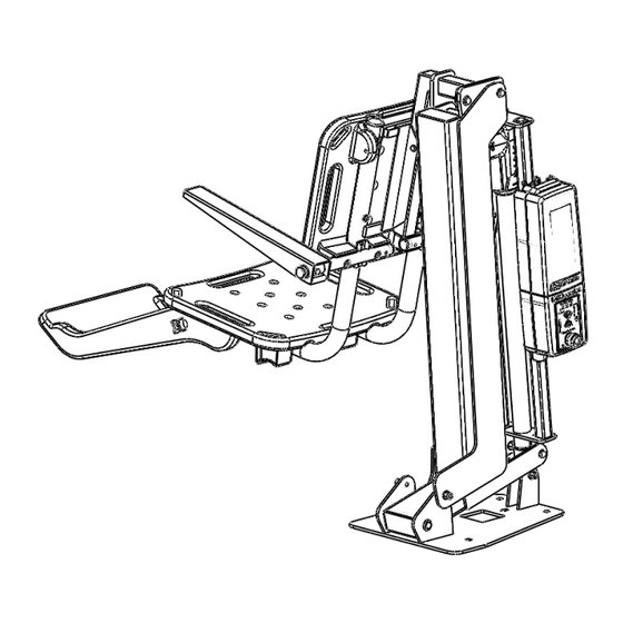
Page 22: Appendix A: Multilift™ Assembly
APPENDIX A: multiLift™ ASSEMBLY *500‐5000 NEW CONSTRUCTION JIG SOLD SEPARATELY *160‐5000 SEAT ASSEMBLY WITH multiLIFT™ FOOTREST, no armrest (160‐5005 multiLIFT™ CHAIR WITH ARMREST and FOOTREST) 700-9000 6.14.13... -
Page 23: Appendix B: Multilift™ Exploded View
APPENDIX B: multiLift™ EXPLODED View 700-9000 6.14.13... - Page 24 ITEM PART Default DESCRIPTION NUMBER / QTY. 14550 BASE ASSEMBLY 14770A ACTUATOR ARM ASSY W/ BUSHINGS 14660A ACTUATOR CAGE ASSY W/ BUSHINGS 14990 CONTOL AXLE ASSY 14880A SEAT ARM ASSY W/ BUSHINGS 14440A SUPPORT ARM W/ BUSHINGS 800-0119 THRST BSHG .375"ID X .75"OD X .0625"LG 800-0106 THRST BSHG .375"ID X .75"OD X .125"LG 05-32-111...
-
Page 25: Appendix C: Multilift™ Chair
APPENDIX C: multiLift™ CHAIR FOOT RESTS ATTACH THE multiLIFT™ FOOTREST USING THE THUMBSCREWS AND 2 ¾” LONG HEX BOLT (800-2042 AND 800-2039) *ARMRESTS (HARDWARE PROVIDED WITH ARMREST CHAIR 160-5005) POSITION THE ARM OVER THE THREE HOLES REAR OF THE BACKREST THAT MATCH THAT OF THE SEAT ARM. -
Page 26: Appendix D: Multilift™ Chair Right To Left Conversion
APPENDIX D: multiLift™ Chair Right to Left Conversion CONTROL AXLE SEAT ARM SUPPORT ACTUATOR Note: Appendix B can be used as a reference for hardware order of assembly. The following directions describe the process for moving the multiLift™ seat from the right (standard) mounting configuration to left mounting configuration. 1. Remove the two lock nuts from the top pivot assembly. - Page 27 6. Remove the 3/8” lock nut that secures the bottom of the Support Arm to the Base Assembly. 7. Slide the Support arm off the stud and set aside. 8. Remove the 1/8” thick thrust bushing from the stud. Control Seat Arm Axle SUPPORT...
- Page 28 15. Remove the White Plastic Cap from the stud on the opposite side of the lift and replace it on the stud from which the Support Arm was removed. Attach the tension arm onto stud with the 1/8” Thrust Bushing placed between the base bracket and Support Arm. Secure the Support Arm using the nylon washer, stainless steel washer and lock nut.
- Page 29 17. With the Control Box secure in place, test the unit by attaching the battery and making sure the lift functions correctly. Check all hardware and make sure it is tightened securely before using the lift. 700-9000 6.14.13...
-
Page 30: Appendix E: New Construction Jig
APPENDIX E: New Construction Jig NEW CONSTRUCTION ANCHOR JIG WHEN ASSEMBLING THE FLUSH DECK ANCHORS TO THE NEW CONSTRUCTION JIG, MAKE SURE THAT THE DISTANCE BETWEEN THE TOP SUFACE OF THE JIG AND THE TOP OF EACH ANCHOR IS 2.5”, AS SHOWN IN THE DIAGRAM ABOVE. * FLUSH DECK ANCHORS (300-6700) SOLD SEPARATE *KIT NUMBER 300-6700A (QTY 4) 700-9000 6.14.13...
Need help?
Do you have a question about the MultiLift and is the answer not in the manual?
Questions and answers