
Related Manuals for FG Wilson PowerWizard 1.0


Summary of Contents for FG Wilson PowerWizard 1.0
- Page 1 PowerWizard 1.0 & 2.0 Control Systems User Manual PowerWizard 1.0 & 2.0 Control Systems User Manual...
- Page 2 PowerWizard 1.0 & 2.0 Control Systems User Manual Important Safety Information Most accidents that involve product operation, maintenance and repair are caused by failure to observe basic safety rules or precautions. An accident can often be avoided by recognizing potentially hazardous situations before an accident occurs.
-
Page 3: Table Of Contents
PowerWizard 1.0 & 2.0 Control Systems User Manual Table of Contents GENERAL INFORMATION ........................4 Introduction ..........................4 Applications ..........................5 PowerWizard Variations (PW1.0 and PW2.0) ................5 PowerWizard Control Module Description ..................6 BASIC OPERATION ..........................7 START Mode .......................... -
Page 4: General Information
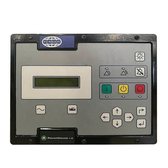
Introduction Figure 1: PowerWizard Control System Panel The controller is available in two versions, PowerWizard 1.0 and PowerWizard 2.0. These two versions are based on different features. This guide is intended to cover the PowerWizard Generating Set Control and its application in generating set systems. -
Page 5: Applications
PowerWizard Variations (PW1.0 and PW2.0) Some of the different features of the two versions, PowerWizard 1.0 and PowerWizard 2.0 are listed in table 1. Controllers Series Features PowerWizard 1.0 PowerWizard 2.0... -
Page 6: Powerwizard Control Module Description
PowerWizard 1.0 & 2.0 Control Systems User Manual PowerWizard Control Module Description Display screen Auto AC overview hot-key Stop DC overview hot-key Up cursor Warning lamp Escape Shutdown lamp Right cursor Alarm acknowledge Enter Lamp test Down cursor Left cursor... -
Page 7: Basic Operation
PowerWizard 1.0 & 2.0 Control Systems User Manual Basic Operation START Mode Press START Key STOP Mode Press STOP Key AUTO Mode Press AUTO Key Figure 3: Basic Operation – Start, Stop and Auto Modes... -
Page 8: Fault / Alarm Reset Process
PowerWizard 1.0 & 2.0 Control Systems User Manual Fault / Alarm Reset Process Fault / Alarm Reset Process Fault / Alarm Reset Fault / Alarm Reset Fault / Alarm Reset. The display will show: Figure 4: Basic Operation – Fault Alarm Reset Process... -
Page 9: User Interface Overview
PowerWizard 1.0 & 2.0 Control Systems User Manual User Interface Overview Function Keys AC Overview hot-key – The AC Overview key will navigate the display to the first screen of AC information. The AC Overview information contains various AC parameters that summarise the electrical operation of the generating set. -
Page 10: Alarm Indicators
PowerWizard 1.0 & 2.0 Control Systems User Manual Alarm Indicators Yellow Warning Light – A flashing yellow light indicates that there are unacknowledged active warnings. A solid yellow light indicates that there are acknowledged warnings active. If there are any active warnings, the yellow light will change from flashing yellow to solid yellow after the Alarm Acknowledge key is pressed. -
Page 11: Detailed Operation
PowerWizard 1.0 & 2.0 Control Systems User Manual Detailed Operation PowerWizard Menu Trees 4.1.1 PowerWizard 1.0 Menu Tree PowerWizard 1.0 Generating Set Control Menu Structure ENG SPEED SENSOR ESCAPE ENTER ERRATIC/LOST 3/17 *2 OR *3 MAIN MENU ACTIVE OCC 1... -
Page 12: Powerwizard 2.0 Menu Tree
PowerWizard 1.0 & 2.0 Control Systems User Manual 4.1.2 PowerWizard 2.0 Menu Tree PowerWizard 2.0 Generating Set Control Menu Structure ENG SPEED SENSOR ESCAPE ENTER ERRATIC/LOST 3/17 *2 OR *3 ACTIVE OCC 1 MAIN MENU ACTIVE EVENTS GENSET CONTROL EVENT LOG... -
Page 13: Technical Operation
PowerWizard 1.0 & 2.0 Control Systems User Manual Technical Operation 4.2.1 Engine Starting Sequence 1. The PowerWizard receives an engine start signal. The signal will be one of four: • The operator presses the Run key • The control is in auto and the remote initiate digital input becomes active •... -
Page 14: Event State
PowerWizard 1.0 & 2.0 Control Systems User Manual 4.2.4 Event State Events in PowerWizard may exist in one of three states: present, active and inactive. Present – The condition causing the event is ongoing and affecting system behaviour. If an event is present it cannot be reset. -
Page 15: Quick Event Resetting
PowerWizard 1.0 & 2.0 Control Systems User Manual 4.2.7 Quick Event Resetting In addition to the above procedure there is also a simplified process for resetting all events. To reset all events: 1. Press the Stop key. 2. Press and hold the Alarm Acknowledge key for three seconds. -
Page 16: Real Time Clock Programming (Powerwizard 2.0)
PowerWizard 1.0 & 2.0 Control Systems User Manual CHANGING SCADA PASSWORD (PowerWizard 2.0 only) – used to set-up, change or disable a SCADA password. Highlight and press enter to proceed to the password entry screen. To set-up or change the password, enter the new password using the cursor keys. -
Page 17: Pct Status
PowerWizard 1.0 & 2.0 Control Systems User Manual The PCT feature consists of seven independent timers. Each timer has the following setpoints (setpoints shown are for PCT #1): • Programmable Cycle Timer #1 Activation Day of the Week. This permits independent selection of each day (Sun >Sat) that the timer will activate... -
Page 18: Additional Features Available
PowerWizard 1.0 & 2.0 Control Systems User Manual Additional Features Available Reduced Power Mode This feature can reduce current draw by approximately a factor of 7. However it is recommended that generating sets at rest or storage for prolonged periods should either have the battery charger or isolator switch option fitted.
Need help?
Do you have a question about the PowerWizard 1.0 and is the answer not in the manual?
Questions and answers
Trying to connect remote start cable to generator panel and automatic transfer switch panel
My 17 kva fg wilson generator set is not starting on automatic mode nor manual mode. You can hear relay clicking but no output to starter solenoid
Generator won't shut down after mains return
Need 12vdc connection for power wizard 1.0
12vdc Relay connection