Table of Contents
Advertisement
Advertisement
Table of Contents

Related Manuals for Whirlpool W11296289


Summary of Contents for Whirlpool W11296289
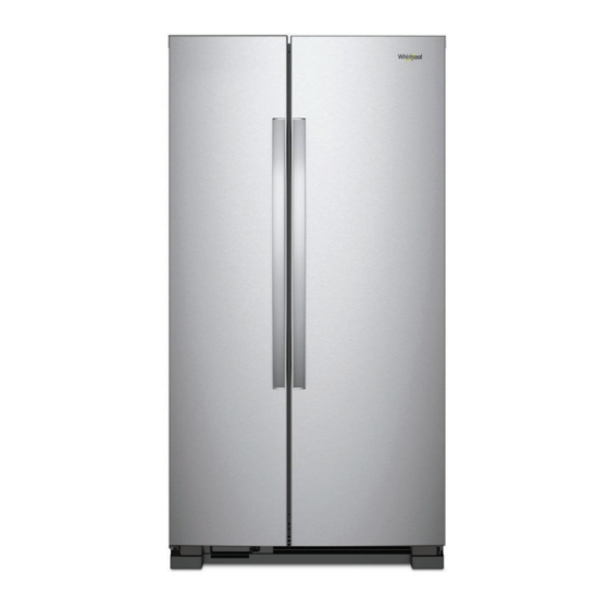
- Page 1 R-126 SERVICE MANUAL Whirlpool®, Maytag®, Amana®, & IKEA® Refrigerators W11296289...
- Page 2 FORWARD This Whirlpool Service Manual (Part No. W11296289), provides the In-Home Service Professional with service information for the “Whripool®, Maytag®, Amana®, and IKEA® Refrigerators.” The Wiring Diagram used in this Service Manual is typical and should be used for training purposes only. Always use the Wiring Diagram supplied with the product tech sheet when servicing the refrigerator.
-
Page 3: Table Of Contents
TABLE OF CONTENTS Whirlpool®, Maytag®, Amana®, & IKEA® Refrigerators SECTION 1: GENERAL INFORMATION ................1-01 REFRIGERATOR SAFETY ........................1-02 PRODUCT SPECIFICATIONS ....................... 1-03 PRODUCT FEATURES ......................... 1-11 MODEL & SERIAL NUMBER LOCATION ..................... 1-12 TECH SHEET LOCATION ........................1-12 MODEL NOMENCLATURE ......................... 1-13 SECTION 2: DIAGNOSTICS ..................2-01... - Page 4 Notes Whirlpool , Maytag , Amana , & IKEA Refrigerators ® ® ® ®...
-
Page 5: Section 1: General Information
GENERAL INFORMATION Section 1: General Information This section provides general safety, parts, and information for the “Whirlpool®, Maytag®, Amana®, and IKEA® Refrigerators.” ■ Refrigerator Safety ■ Product Specifications ■ Product Feature • Control Panel ■ Model & Serial Label •... -
Page 6: Refrigerator Safety
SAVE THESE INSTRUCTIONS Whirlpool , Maytag , Amana , & IKEA Refrigerators ®... -
Page 7: Product Specifications
Door Style Contour Door Swing Handle Color Black/Stainless Steel/White Handle Material Metal Handle Type Reach Through Handle Hidden Hinge Number of Doors Levelers 2 Black Wheels 4-Natural Whirlpool , Maytag , Amana , & IKEA Refrigerators ® ® ® ®... - Page 8 Exterior Ice and Water Dispenser Options Filtered Water Measured/Metered Fill Types of Ice Crushed/Cubed Dispenser Pad Color Black Icemaker Icemaker Factory Installed Icemaker Location Freezer Electrical Amps Volts Whirlpool , Maytag , Amana , & IKEA Refrigerators ® ® ® ®...
- Page 9 GENERAL INFORMATION Whirlpool® 36" Wide Side by Side Refrigerator - 25 Cu Ft AHAM Volumes and Shelf Area Freezer Volume (Cu Ft) 9.11 Refrigerator Volume (Cu Ft) 15.46 Total Volume (Cu Ft) 24.6 Dimensions Capacity (FT3, Cu Ft) 24.57 Cabinet Width (IN, inches)
- Page 10 No Dispenser/Exterior Ice and Water Dispenser Options Filtered Water Ice Dispenser Lock Night Light Types of Ice Crushed/Cubed Icemaker Icemaker Optional/Factory Installed Icemaker Kit Part Number ECKMF95 Icemaker Location Freezer Electrical Whirlpool , Maytag , Amana , & IKEA Refrigerators ® ® ® ®...
- Page 11 GENERAL INFORMATION Whirlpool® 33" Wide Side by Side Refrigerator - 22 Cu Ft AHAM Volumes and Shelf Area Freezer Volume (Cu Ft) 7.07 Refrigerator Volume (Cu Ft) 14.65 Total Volume (Cu Ft) 21.7 Dimensions Capacity (FT3, Cu Ft) 21.72 Cabinet Width (IN, inches)
- Page 12 1 Full-Width Lower Plastic Door Bins 4 Fixed Full-Width Light Dispenser Dispenser Type No Dispenser Icemaker Icemaker Optional Icemaker Location Freezer Icemaker Kit Part Number ECKMF95 Electrical Amps Volts Whirlpool , Maytag , Amana , & IKEA Refrigerators ® ® ® ®...
- Page 13 GENERAL INFORMATION Whirlpool® 33" Wide Side by Side Refrigerator - 21 Cu Ft AHAM Volumes and Shelf Area Freezer Volume (Cu Ft) 6.77 Refrigerator Volume (Cu Ft) 14.65 Total Volume (Cu Ft) 21.4 Dimensions Capacity (FT3, Cu Ft) 21.4 Cabinet Width (IN, inches)
- Page 14 Exterior Ice and Water Dispenser Options Filtered Water Ice Dispenser Lock Measured/Metered Fill Night Light Types of Ice Crushed/Cubed Icemaker Icemaker Factory Installed Icemaker Location Freezer Electrical 1-10 Whirlpool , Maytag , Amana , & IKEA Refrigerators ® ® ® ®...
-
Page 15: Product Features
Press Freezer Temp again to adjust the set point. The setting will increase by 1 bar with each press of the button, returning to 1 bar after reaching 5 bar. After 2 minutes of inactivity, any changes will be saved and the display will return to the home screen. Whirlpool , Maytag , Amana , &... -
Page 16: Model & Serial Number Location
GENERAL INFORMATION Model & Serial Number Location Tech Sheet Location 1-12 Whirlpool , Maytag , Amana , & IKEA Refrigerators ® ® ® ®... -
Page 17: Model Nomenclature
GENERAL INFORMATION Model Nomenclature MODEL NUMBER INTERNATIONAL SALES OR MARKETING CHANNEL Brand W = Whirlpool Platform R = Freestanding Refrigeration S = Specialty Refrigeration U = Undercounter Refrigeration Z = Freestanding Freezer Sub Platform/Fuel T = Top Freezer S = Side by Side... - Page 18 GENERAL INFORMATION Notes 1-14 Whirlpool , Maytag , Amana , & IKEA Refrigerators ® ® ® ®...
-
Page 19: Section 2: Diagnostics
DIAGNOSTICS Section 2: Diagnostics This section provides diagnostic mode and sales mode information for the “Whirlpool®, Maytag®, Amana®, and IKEA® Refrigerators.” ■ Safety ■ Diagnostics Mode ■ Sales Mode Whirlpool , Maytag , Amana , & IKEA Refrigerators ® ®... -
Page 20: Safety
Before removing the part from its package, touch the antistatic bag to a green ground connection point or unpainted metal in the appliance. Avoid touching electronic parts or terminal contacts; handle electronic control assembly by edges only. When repackaging failed electronic control assembly in antistatic bag, observe above instructions. Whirlpool , Maytag , Amana , & IKEA Refrigerators ®... -
Page 21: Diagnostics Mode
550 - 650 Evaporator Fan Motor See Note 2 - 9 See Note 2 - 9 Condenser Fan Motor See Note 3 - 12 See Note 3 - 12 Whirlpool , Maytag , Amana , & IKEA Refrigerators ® ® ® ®... - Page 22 The LEDs on the FREEZER TEMP section will show the step number while the LEDs above REFRIGERATION TEMP section will show the feedback. Steps 29 to 35 apply only for models with twist tray maker in the door (IDI). Whirlpool , Maytag , Amana , &...
- Page 23 Entry: Display step number & turn ON ● ● ● ● & Cond Fan the Cond fan. LED1 LED2 LED3 LED4 LED5 Do: Service user to monitor load. Exit: Load off. NONE Whirlpool , Maytag , Amana , & IKEA Refrigerators ® ® ® ®...
- Page 24 Do: User to press ice paddle. Service ● user to monitor the display feedback. LED6 LED7 LED8 LED9 LED10 Exit: N/A. NOTE: No water is dispensed in this step. NONE Whirlpool , Maytag , Amana , & IKEA Refrigerators ® ® ® ®...
- Page 25 LED6 LED7 LED8 LED9 LED10 after water fill test to leave tray empty when finishing service. Ice bucket must be in place to run this test. NONE Whirlpool , Maytag , Amana , & IKEA Refrigerators ® ® ® ®...
- Page 26 6 from the above table. Water Filter Reset Hold 3 sec NOTE: If step 6 shows all LEDs blank means that board drivers and sensors are working correctly. Whirlpool , Maytag , Amana , & IKEA Refrigerators ®...
-
Page 27: Sales Demo Mode
Press (LIGHT) Key in show room Behavior will be same as normal operation. Press (ICE TYPE) key in show room Ice-type LED changes between crush when the user presses the mode. Ice Type key. Whirlpool , Maytag , Amana , & IKEA Refrigerators ®... - Page 28 2. Hold DOOR SWITCH to simulate door close. 3. Press and hold (TEMP SETTING) for 3 seconds. Power interval during showroom mode. UI returns to Normal mode after a power reset or power failure. 2-10 Whirlpool , Maytag , Amana , & IKEA Refrigerators ®...
- Page 29 DIAGNOSTICS For Service Technician Use Only Notes Whirlpool , Maytag , Amana , & IKEA Refrigerators 2-11 ® ® ® ®...
- Page 30 DIAGNOSTICS For Service Technician Use Only Notes 2-12 Whirlpool , Maytag , Amana , & IKEA Refrigerators ® ® ® ®...
-
Page 31: Section 3: Component Testing
COMPONENT TESTING Section 3: Component Testing This section provides the wiring diagram and component location for the “Whirlpool®, Maytag®, Amana®, and IKEA® Refrigerators.” ■ Safety ■ Wiring Diagram ■ Component Location Whirlpool , Maytag , Amana , & IKEA Refrigerators ®... -
Page 32: Safety
Before removing the part from its package, touch the antistatic bag to a green ground connection point or unpainted metal in the appliance. Avoid touching electronic parts or terminal contacts; handle electronic control assembly by edges only. When repackaging failed electronic control assembly in antistatic bag, observe above instructions. Whirlpool , Maytag , Amana , & IKEA Refrigerators ®... -
Page 33: Wiring Diagram
12 VDC Pulse Damper Stepper Motor coil B - P11-3 P11-4 12 VDC Output to damper Heater VOLTAGE TEST POINTS MINOTAUR J1-1 J1-4 12.7 VDC Output to User Interface J1-2 GY DATA COMMUNICATION Whirlpool , Maytag , Amana , & IKEA Refrigerators ® ® ® ®... - Page 34 GN/YL RD/WH RD/WH BK RIBBED GN/YL GN/YL GN/YL GN/YL BK SMOOTH GN/YL GY/OR GY/OR BK/WH WH/TN YL/RD YL/RD RC LAMP TOP RC LAMP MID1 RC LAMP MID2 Whirlpool , Maytag , Amana , & IKEA Refrigerators ® ® ® ®...
- Page 35 JP1-6 120 VAC Output Defrost Heater when defrosting JP1-3 JP1-6 120 VAC Input Constant from Power Cord JP1-4 JP1-6 120 VAC Output to Compressor and Fans when cooling Whirlpool , Maytag , Amana , & IKEA Refrigerators ® ® ®...
- Page 36 TO_SWITCH_PACK_ASSY DISP_GND TO COMPRESSOR TO COND FAN TO LED DISPENSER DISPENSER HEATER LED DISPENSER TO_ICE_PADEL TO_WATER_PADEL COMPRESOR COND FAN ICE PADEL WATER PADEL PADDLE HARNESS UNIT HARNESS Whirlpool , Maytag , Amana , & IKEA Refrigerators ® ® ® ®...
- Page 37 JP1-6 120 VAC Output Defrost Heater when defrosting JP1-3 JP1-6 120 VAC Input constant from Power Cord JP1-4 JP1-6 120 VAC Output to Compressor and Fans when cooling Whirlpool , Maytag , Amana , & IKEA Refrigerators ® ® ®...
- Page 38 BK SMOOTH OPTIONAL TO ICE MAKER WATER VALVE ICE MAKER WATER VALVE TO CHASSIS GROUND TO COMPRESSOR TO COND FAN TO COMP GND COMPRESSOR COND FAN MOTOR Whirlpool , Maytag , Amana , & IKEA Refrigerators ® ® ® ®...
-
Page 39: Component Location
For Service Technician Use Only Component Location A. Condenser Fan E. Athena Control Board B. Condenser F. Front Door Dispenser Unit C. Freezer Evaporator G. Compressor D. Auger Ice Dispenser Whirlpool , Maytag , Amana , & IKEA Refrigerators ® ® ® ®... - Page 40 COMPONENT TESTING For Service Technician Use Only Notes 3-10 Whirlpool , Maytag , Amana , & IKEA Refrigerators ® ® ® ®...
-
Page 41: Section 4: Component Access
COMPONENT ACCESS Section 4: Component Access This section provides service parts access, removal, and replacement instructions for the “Whirlpool®, Maytag®, Amana®, and IKEA® Refrigerators.” n Removing the front wheel n Accessing the interior of the unit n Removing the damper... -
Page 42: Removing The Front Wheel
Then remove the pin at this point you can remove the wheel assembly. 2. Below picture shows level screw. 5. Below picture shows the wheel out of the unit. A. Level screw Whirlpool , Maytag , Amana , & IKEA Refrigerators ®... -
Page 43: Accessing Interior Of Unit
• The controls are all on the dispenser. Air Return Water Tank Thermistor Tab to push on to release Whirlpool , Maytag , Amana , & IKEA Refrigerators ® ® ®... - Page 44 4. The cover will come off and then you can access the wiring harness. 5. The damper will come out. The damper has both RC and FC thermistor on the harness. Whirlpool , Maytag , Amana , & IKEA Refrigerators ®...
-
Page 45: Removing The Freezer Shelf
Do this for both front and back. Note: At this point, the shelf can be dropped down and removed. To put the shelf back in just reverse the process. Whirlpool , Maytag , Amana , & IKEA Refrigerators ®... - Page 46 5. Below picture shows auger motor and cube/crushed coil. A. Auger Solenoid B. Auger Drive Motor 3. Below picture shows freezer components. Defrost thermistor goes on the cap tube side. Whirlpool , Maytag , Amana , & IKEA Refrigerators ®...
-
Page 47: Accessing The Dispenser Area (Removing Ui)
Electrical Shock Hazard Disconnect power before servicing. Replace all parts and panels before operating. Failure to do so can result in death or electrical shock. 1. Below picture shows the dispenser area. Whirlpool , Maytag , Amana , & IKEA Refrigerators ®... - Page 48 6. To remove ice door, remove water line for the holder. Remove the upper screws then pry tabs. 4. You now have access to the wiring for UI. Whirlpool , Maytag , Amana , & IKEA Refrigerators ®...
- Page 49 COMPONENT ACCESS 7. Below pictures show the ice chute assembly. Whirlpool , Maytag , Amana , & IKEA Refrigerators ® ® ® ®...
-
Page 50: Accessing The Machine Compartment
5. To remove the Dual Water Valve, remove the two 1/4" (6.4 mm) hex head screws, disconnect the wiring and water lines then lift out. A. Filter Dryer B. Dual water valve 4-10 Whirlpool , Maytag , Amana , & IKEA Refrigerators ®... - Page 51 COMPONENT ACCESS 6. Below picture shows high voltage board. Whirlpool , Maytag , Amana , & IKEA Refrigerators 4-11 ® ® ® ®...
- Page 52 INFORMATION SOURCES IN THE UNITED STATES: FOR PRODUCT SPECIFICATIONS AND WARRANTY INFORMATION CALL: FOR WHIRLPOOL PRODUCTS: 1-800-253-1301 FOR TECHNICAL ASSISTANCE WHILE AT THE CUSTOMER’S HOME CALL: THE TECHNICAL ASSISTANCE LINE: 1-800-832-7174 HAVE YOUR STORE NUMBER READY TO IDENTIFY YOU AS AN...
Need help?
Do you have a question about the W11296289 and is the answer not in the manual?
Questions and answers