
Related Manuals for Deif PPM 300


Summary of Contents for Deif PPM 300
- Page 1 PPM 300 DEIF A/S · Frisenborgvej 33 · DK-7800 Skive · Tel.: +45 9614 9614 · Fax: +45 9614 9615 · info@deif.com · www.deif.com isenborgvej 33 · DK-7800 Skive · Tel.: +45 9614 9614 · Fax: +45 9614 9615 · info@deif.com · www.deif.com 14 9614 ·...
-
Page 2: Table Of Contents
1.1.1 Intended users of the Operator's manual ..................................1.1.2 Software versions ............................................1.1.3 Technical support ............................................1.1.4 List of technical documentation for PPM 300 ................................1.2 Warnings and safety ..............................................1.2.1 Safety during installation and operation ..................................1.2.2 Automatic and remote-controlled starts .................................. - Page 3 PPM 300 Operator's manual 4189340910 UK 4.2.4 Stopping the genset ..........................................4.2.5 Closing the genset breaker ......................................... 4.2.6 Opening the genset breaker ....................................... 4.2.7 Setting genset start and stop priority .................................... 4.3 EMERGENCY genset controller basic actions ................................4.3.1 Introduction to operating the EMERGENCY genset controller .........................
- Page 4 PPM 300 Operator's manual 4189340910 UK 7. Configure 7.1 Introduction ................................................... 7.1.1 About configure ............................................7.2 Priority ....................................................7.2.1 View or configure priority ........................................7.3 Counters ..................................................7.3.1 View or configure counters ........................................7.4 Parameters ..................................................7.4.1 View or configure parameters ......................................
- Page 5 PPM 300 Operator's manual 4189340910 UK 8.2.7 Out of service alarm(s) ........................................9. Live data 9.1 Introduction ................................................9.1.1 Live data ................................................. 9.2 Live data ..................................................9.2.1 View the Live data ........................................... 9.2.2 Live data counters ........................................... 10. Tools 10.1 Introduction ................................................
- Page 6 PPM 300 Operator's manual 4189340910 UK 13.2.2 Troubleshooting the system under SWBD control ............................13.3 Troubleshooting alarms ..........................................13.3.1 Troubleshooting alarms ........................................13.3.2 Troubleshooting analogue input sensor failures ............................... 13.4 Engine ..................................................... 13.4.1 Start failure ..............................................13.4.2 Overspeed # ..............................................
-
Page 7: Introduction
PC software 1.0.1.x 1.1.3 Technical support You can read about service and support options on the DEIF website, www.deif.com. You can also find contact details on the DEIF website. You have the following options if you need technical support: • Help: The display unit includes context-sensitive help. -
Page 8: List Of Technical Documentation For Ppm 300
PPM 300 Operator's manual 4189340910 UK 1.1.4 List of technical documentation for PPM 300 Document Contents • System description and functions • Technical specifications • Each controller type Data sheet ◦ Applications, hardware, functions and protections • Hardware modules, display unit, and accessories •... -
Page 9: Warnings And Safety
PPM 300 Operator's manual 4189340910 UK Document Contents • Controller equipment (push-buttons and LEDs) • Operating the system Operator's manual • Alarms and log • Using the display unit • Troubleshooting and maintenance PICUS manual Using PICUS and CustomLogic • Modbus address list ◦... -
Page 10: Controller Power Supply
1.3 Legal information 1.3.1 Third party equipment DEIF takes no responsibility for the installation or operation of any third party equipment, including the genset. Contact the genset company if you have any doubt about how to install or operate the genset. -
Page 11: Warranty
This product contains open source software licensed under, for example, the GNU General Public License (GNU GPL) and GNU Lesser Public License (GNU LGPL). The source code for this software can be obtained by contacting DEIF at support@deif.com. DEIF reserves the right to charge for the cost of the service. -
Page 12: Overview Of The System
2.1 Overview 2.1.1 Operating the PPM 300 controllers The PPM 300 controllers ensure that the power required is available and that the system is protected for typical marine applications. Only qualified people may install and commission the controllers. After the controllers are installed and commissioned, they are easy to operate. -
Page 13: Operator Messages
PPM 300 Operator's manual 4189340910 UK PICUS is the PC programming and monitoring tool, available from DEIF free of charge. The operator can connect a computer with PICUS to the controller by using a direct connection. The operator can then log into the controller. When the operator logs on, they can use PICUS to monitor operation, send commands that correspond to the push-button actions, manage alarms, and see or change the controller configuration. - Page 14 PPM 300 Operator's manual 4189340910 UK Status text Description BTB in operation The bus tie breaker is closed. ● Displays the remaining time (in seconds) Busbar OK in - before the emergency genset begins the ● remaining time emergency genset stop procedure after a blackout is solved.
- Page 15 PPM 300 Operator's manual 4189340910 UK Status text Description Shown when the "Block load-dependent Load-dependent stop stop" function is activated on the shaft ● ● blocked generator controller. The gensets that are connected to the Load sharing busbar are sharing the load symmetrically ●...
- Page 16 PPM 300 Operator's manual 4189340910 UK Status text Description The shaft generator is producing power, SG in operation (base and shaft generator breaker is closed. The ● load) base load parameter is activated. Power take home has been activated, and SG in PTH operation ●...
-
Page 17: Operator Information Messages
PPM 300 Operator's manual 4189340910 UK 2.2.2 Operator information messages Table 2.2 Controller types Icon Notes GENSET controller EMERGENCY genset controller SHAFT generator controller SHORE connection controller BUS TIE breaker controller Operator info Additional information While the controller is under switchboard... - Page 18 PPM 300 Operator's manual 4189340910 UK Operator info Additional information There is an overload present on the Available power too busbar the genset is connecting to. ● Cancelling the Close breaker command will cause a blackout. Blackout start block The Block blackout start function is active.
- Page 19 PPM 300 Operator's manual 4189340910 UK Operator info Additional information While the controller is under switchboard Engine block not controller, operator actions cannot be ● ● possible in SWBD performed from the controller interfaces. The command has already been received.
- Page 20 PPM 300 Operator's manual 4189340910 UK Operator info Additional information GB is open The Generator breaker is open. ● ● GB is synchronising The Generator breaker is synchronising. ● ● While the controller is under switchboard GB open and stop not controller, operator actions cannot be ●...
- Page 21 PPM 300 Operator's manual 4189340910 UK Operator info Additional information The Power take home parameter is PTH mode activates activated while the shaft generator breaker when breaker is ● is closed. Open the shaft generator opened breaker to start power take home mode.
- Page 22 PPM 300 Operator's manual 4189340910 UK Operator info Additional information The Shaft generator breaker close has SGB close cancelled ● been cancelled. While the controller is under switchboard SGB close not controller, operator actions cannot be ● possible in SWBD performed from the controller interfaces.
- Page 23 PPM 300 Operator's manual 4189340910 UK Operator info Additional information The Block tie breaker close function is not TB close unblocked ● active. The opening of the Tie breaker has been TB open cancelled ● cancelled. While the controller is under switchboard...
-
Page 24: Controller Equipment
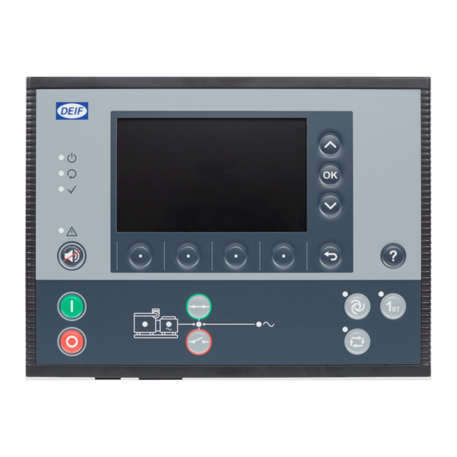
PPM 300 Operator's manual 4189340910 UK 3. Controller equipment 3.1 Display unit 3.1.1 Introduction to the display unit The front of the display unit consists of a top part and a bottom strip. Figure 3.1 Display unit parts Top part Bottom strip The LEDs and push-buttons for the top part are the same for all controller types. -
Page 25: Display Unit Leds And Push-Buttons
PPM 300 Operator's manual 4189340910 UK 3.1.2 Display unit LEDs and push-buttons The top part of the front of the display unit is the same for all controller types. It includes LEDs that show the controller status and a push-button to silence the alarm horn. The other push-buttons allow the operator to see controller information on the display unit screen. -
Page 26: Genset Controller Leds And Push-Buttons
PPM 300 Operator's manual 4189340910 UK INFO The display unit LEDs show the status of the controller, and not the status of the display unit. The display unit screen is lit if the display unit has power. The display unit screen is not lit if there is no power supply. - Page 27 PPM 300 Operator's manual 4189340910 UK Table 3.3 GENSET controller LED functions No. Name Function Green: There is running feedback. Oil pressure, RPM, frequency above configured limit. Engine Green (flashing): Engine is becoming ready. OFF: The engine is not running, or there is no running feedback.
-
Page 28: Emergency Genset Controller Leds And Push-Buttons
PPM 300 Operator's manual 4189340910 UK Table 3.4 GENSET controller push-button functions No. Name Function SEMI mode: The controller starts the genset start sequence. Genset start AUTO mode or Switchboard control: The controller ignores the input from this push-button. SEMI mode: The controller starts the genset stop sequence. - Page 29 PPM 300 Operator's manual 4189340910 UK No. Name Function Green: The breaker is closed. Yellow: The breaker spring is charging (only applies to a compact breaker). Yellow (flashing): The controller is synchronising or de-loading the breaker. Breaker Red: The controller tripped the breaker, and the trip alarm is unacknowledged and/or the alarm condition is still present.
-
Page 30: Shaft Generator Controller Leds And Push-Buttons
PPM 300 Operator's manual 4189340910 UK Table 3.6 EMERGENCY genset controller push-button functions No. Name Function SEMI mode: The controller starts the genset start sequence. Genset start AUTO mode or Switchboard control: The controller ignores the input from this push-button. - Page 31 PPM 300 Operator's manual 4189340910 UK Table 3.7 SHAFT generator controller LED functions No. Name Function Green: The generator voltage and frequency are OK, and the controller can close the breaker. Green (flashing): The generator voltage and frequency are OK, but the V&Hz OK timer is still running.
-
Page 32: Shore Connection Controller Leds And Push-Buttons
PPM 300 Operator's manual 4189340910 UK 3.1.6 SHORE connection controller LEDs and push-buttons The bottom strip of the front of the display unit is customised for the SHORE connection controller. It includes LEDs that show the equipment and controller status, as well as push-buttons for operator actions. -
Page 33: Bus Tie Breaker Controller Leds And Push-Buttons
PPM 300 Operator's manual 4189340910 UK SHORE connection controller push-buttons Figure 3.10 SHORE connection controller display unit push-buttons Table 3.10 SHORE connection controller push-button functions Name Function PMS control: The controller starts the breaker close sequence. Close breaker Switchboard control: The controller ignores the input from this push-button. - Page 34 PPM 300 Operator's manual 4189340910 UK Table 3.11 BUS TIE breaker controller LED functions No. Name Function Green: The busbar A voltage and frequency are OK, and the controller can close the breaker. Green (flashing): The busbar A voltage and frequency are OK, but the V&Hz OK timer is still running.
-
Page 35: Controller Rack
PPM 300 Operator's manual 4189340910 UK 3.2 Controller rack 3.2.1 Rack LEDs You will normally not be able to see the controller rack, since it is normally in an enclosed switchboard. However, the controller rack includes LEDs that can be useful for troubleshooting, and these are described here. -
Page 36: Pcm3.1 Leds
PPM 300 Operator's manual 4189340910 UK 3.2.3 PCM3.1 LEDs Symbol Name Function Green: The Ethernet connection is OK. DEIF network Green (flashing): There is data traffic in the Ethernet connection. PCM3.1 port 1* OFF: There is no Ethernet connection, or the Ethernet connection is not OK. -
Page 37: Operating The System
INFO DEIF recommends that the operator actions that depend on the system design and configuration are documented. See the Designer's handbook for more information about the system-specific functions that are available by default in the controller. - Page 38 PPM 300 Operator's manual 4189340910 UK Mode Procedure To change to AUTO mode from SEMI mode: 1. Operator action: Press to select AUTO mode. • System response: The LED next to is green when the controller is in AUTO mode.
-
Page 39: Starting The Genset
PPM 300 Operator's manual 4189340910 UK 4.2.3 Starting the genset Mode Procedure When the controller is in AUTO mode, the genset start is controlled automatically and the display unit AUTO push-buttons are disabled. If the power management system calculates that more power is required, the controller automatically starts the genset(s), according to the genset priority order. -
Page 40: Closing The Genset Breaker
PPM 300 Operator's manual 4189340910 UK 4.2.5 Closing the genset breaker Mode Procedure When the controller is in AUTO mode, the genset breaker is controlled automatically and the display unit push-buttons are disabled. If the power management system calculations show that more power is... -
Page 41: Setting Genset Start And Stop Priority
PPM 300 Operator's manual 4189340910 UK 4.2.7 Setting genset start and stop priority For efficiency or maintenance reasons, you might want certain gensets to automatically run as much as possible, and others to run at little as possible. The power management system has a priority order for the gensets to enable you to do this. If a genset start is needed, the power management system starts the first non-running genset in the priority order. - Page 42 PPM 300 Operator's manual 4189340910 UK Mode Procedure To change to AUTO mode from SEMI mode: 1. Operator action: Press to select AUTO mode. • System response: The LED next to is green when the controller is in AUTO mode.
-
Page 43: Starting The Emergency Genset
PPM 300 Operator's manual 4189340910 UK 4.3.3 Starting the emergency genset Mode Procedure When the controller is in AUTO mode, the emergency genset start is controlled automatically and the AUTO display unit push-buttons are disabled. To start the emergency genset: 1. -
Page 44: Closing The Emergency Genset Breaker
PPM 300 Operator's manual 4189340910 UK INFO The switchboard equipment is third-party equipment. The switchboard might not include a button to stop the genset. 4.3.5 Closing the emergency genset breaker INFO The EMERGENCY genset controller display unit has two sets of breaker push-buttons. The emergency genset breaker push-buttons are on the left, closest to the genset pictogram. -
Page 45: Closing The Tie Breaker
PPM 300 Operator's manual 4189340910 UK Mode Procedure When the controller is in AUTO mode, the emergency genset breaker is controlled automatically and the display unit push-buttons are disabled. AUTO After a blackout, the controller will automatically disconnect and stop the emergency genset when there is a stable voltage on the main busbar. -
Page 46: Opening The Tie Breaker
PPM 300 Operator's manual 4189340910 UK Mode Procedure When the controller is in AUTO mode, the tie breaker is controlled automatically and the display unit push- buttons are disabled. AUTO After a blackout, when stable power is restored on the main busbar, the power management system automatically synchronises to the main busbar and closes the tie breaker. -
Page 47: Emergency Genset Test Function
PPM 300 Operator's manual 4189340910 UK Mode Procedure When the controller is in AUTO mode, the tie breaker is controlled automatically and the display unit push- AUTO buttons are disabled. To open the tie breaker: 1. Operator action: Press to open the tie breaker. -
Page 48: Closing The Shaft Generator Breaker
PPM 300 Operator's manual 4189340910 UK Blackout response If there is a blackout, the PMS automatically follows the blackout recovery sequence to start and connect gensets, in order to restore power. If this does not succeed, as part of the blackout recovery, if auto close is enabled, the PMS attempts to close the shaft generator breaker. -
Page 49: Opening The Shaft Generator Breaker
PPM 300 Operator's manual 4189340910 UK 4.4.3 Opening the shaft generator breaker Control Procedure When the operator opens the shaft generator breaker, the power management system transfers the load from the shaft generator to the gensets. There must therefore be enough gensets available, with enough capacity to take over the shaft generator load. -
Page 50: Closing The Shore Connection Breaker
PPM 300 Operator's manual 4189340910 UK 4.5.2 Closing the shore connection breaker Control Procedure When the operator closes the shore connection breaker, the power management system transfers the load from the gensets to the shore connection. The shore connection must therefore be live and have enough capacity to take over the genset load. -
Page 51: Opening The Shore Connection Breaker
PPM 300 Operator's manual 4189340910 UK 4.5.3 Opening the shore connection breaker Control Procedure When the operator opens the shore connection breaker, the power management system transfers the load from the shore connection to the gensets. There must therefore be enough gensets available, with enough capacity to take over the shore connection load. -
Page 52: Opening The Bus Tie Breaker
PPM 300 Operator's manual 4189340910 UK Control Procedure To close the bus tie breaker: 1. Operator action: Press to close the bus tie breaker. a. System response: The power management system synchronises busbar A and busbar B. During synchronisation, the breaker LED is yellow (flashing). -
Page 53: Using The Display Unit
5.1.1 About the display unit The display unit provides you quick and easy access to both operating and configuration information for the controller. Figure 5.1 Display unit DU 300 example (PPM 300) Item Notes Displays the current controller status text. This varies depending upon the operation of the controller. -
Page 54: About The Soft Keys
PPM 300 Operator's manual 4189340910 UK Figure 5.2 Status bar example Item Notes Displays the current controller status text. This varies depending upon the operation of the controller. Controller status text See Operator messages, Controller status texts for more information. - Page 55 PPM 300 Operator's manual 4189340910 UK Soft key Area Notes Virtual keyboard Deletes the previous character. Log on Views additional user information. User info Log on Log off the current user. Log off Log on Change displayed language. Language Log on Allows a reset of the display unit.
-
Page 56: About The Virtual Keyboard
PPM 300 Operator's manual 4189340910 UK 5.1.4 About the virtual keyboard The display unit features a virtual keyboard, which is used to enter the information for the controller settings or features. The virtual keyboard can display characters for lowercase and uppercase letters, numbers or symbols. -
Page 57: View Help
PPM 300 Operator's manual 4189340910 UK 5.1.5 View help View help for the page you are reading by pressing the help button. You can view help for the page your viewing by pressing Help Figure 5.4 Example help You can scroll the displayed information by pressing Up... -
Page 58: Log On
PPM 300 Operator's manual 4189340910 UK 6. Log on 6.1 Permissions 6.1.1 About permissions The controller is protected by group and user permissions, which allow access to the functionality of the controller. To access the controller you must log on by using a user and password. The user has associated permissions to the controller and software. -
Page 59: Log Off
PPM 300 Operator's manual 4189340910 UK Figure 6.1 Example log on screen Log on to controller To log on the controller, perform the following steps: 1. Select Log on, from the Home menu, to view the available users for the controller. -
Page 60: Language
PPM 300 Operator's manual 4189340910 UK Figure 6.2 Example log off screen To log on the controller, perform the following steps: 1. Select Log on, from the Home menu. 2. Select Log off • The logged on user is now logged off. -
Page 61: Reset
PPM 300 Operator's manual 4189340910 UK By changing the display language, all of the menus, options, and help become translated automatically. INFO The master language is always available to select, but it cannot be modified. Figure 6.3 Example of language change You can then operate the display in your desired language. -
Page 62: User Info
PPM 300 Operator's manual 4189340910 UK INFO When the display unit starts, it connects to the controller that its Ethernet cable is connected to. If you unplug the Ethernet cable and move it to a different controller, the display unit uses the network to resume its connection to the original controller. -
Page 63: Configure
PPM 300 Operator's manual 4189340910 UK 7. Configure 7.1 Introduction 7.1.1 About configure The configure menu allows you to do the following: View and change the genset priorities. View, set, or reset the counter information. Configure the I/O settings. Configure the parameter settings. -
Page 64: Counters
PPM 300 Operator's manual 4189340910 UK Figure 7.1 Example of genset priority changes Change priority To change the priorities: 1. Select Configure, from the Home menu. 2. Select Priorities to view and change the genset priorities. • The following columns are visible: ◦... - Page 65 PPM 300 Operator's manual 4189340910 UK INFO You must be logged on with a user with the necessary permission to change the counter information. If you are not logged on, you are asked if you wish to log on. View the counter information 1.
- Page 66 PPM 300 Operator's manual 4189340910 UK INFO If you are not already logged on, you are prompted to do so. • A confirmation is displayed on screen. • 3. You can now either: • Confirm the reset, by pressing OK •...
- Page 67 PPM 300 Operator's manual 4189340910 UK INFO If you are not already logged on, you are prompted to do so. • The virtual keyboard is shown on the display. • 3. Enter the required counter value, and select Write • A confirmation is displayed on screen: ◦...
-
Page 68: Parameters
PPM 300 Operator's manual 4189340910 UK 7.4 Parameters 7.4.1 View or configure parameters Configure parameter settings under Configure > Parameters. You can configure the parameters for both system settings and alarm settings. The parameters are organised into categories and groups:... -
Page 69: Input/Output
PPM 300 Operator's manual 4189340910 UK 5. Highlight the parameter group you wish to open, by pressing Up or Down 6. Select the highlighted parameter group by pressing OK • The parameter settings are shown on the display. 7. To highlight the parameter, select Up... -
Page 70: View Or Configure Hardware Module I/O Terminals
PPM 300 Operator's manual 4189340910 UK INFO The hardware modules shown vary depending upon controller type or hardware modules installed. The hardware selection screen shows the same hardware modules as you have installed in the controller. Figure 7.3 Example select hardware module INFO Basic details about the available I/Os on the module are shown at the right. -
Page 71: I/O Terminal Settings
PPM 300 Operator's manual 4189340910 UK Figure 7.4 Example I/O configuration terminals If a terminal has already had configured for either a Function or Alarm, the terminal is marked with grey dot INFO The actual terminal types shown depend upon the type of hardware module selected or installed. -
Page 72: Digital Input (Di)
PPM 300 Operator's manual 4189340910 UK Figure 7.5 Example hardware module terminals for a digital input (DI) Here you can configure various settings for the terminal, subject to the type of terminal and hardware module selected. INFO The actual features you can select or configure are also subject to the type of hardware module you have selected. -
Page 73: Configure Function(S)
PPM 300 Operator's manual 4189340910 UK • Write 2. Enter the required I/O name and select Write 7.6.2 Configure function(s) The functions available are organised in to categories and groups, which is similar to a tree structure view. Selecting a function 1. - Page 74 PPM 300 Operator's manual 4189340910 UK • 1. Highlight a previously unused alarm, by pressing Up or Down 2. Select the alarm by pressing OK • Selected alarm(s) are shown with a solid box. Edit 3. Select Edit • Details of the alarm settings are shown on the display for you to configure.
- Page 75 PPM 300 Operator's manual 4189340910 UK Next ◦ To confirm the changes, select Next ◦ If the setting is a selection, pressing OK displays an available list of selection options. ◦ Highlight the option required, by pressing Up or Down ◦...
- Page 76 PPM 300 Operator's manual 4189340910 UK • a. Highlight the required alarm setting, by pressing Up or Down b. To change the setting, press OK ◦ If the setting is Enable or Not enabled, pressing OK toggles either Enable or Not enabled.
-
Page 77: Digital Output (Do)
PPM 300 Operator's manual 4189340910 UK 7.7 Digital output (DO) 7.7.1 Configure I/O name To rename the input or output name: I/O name 1. Select I/O name • The virtual keyboard is displayed on screen to edit the I/O name. -
Page 78: Configure Function(S)
PPM 300 Operator's manual 4189340910 UK Figure 7.6 Example relay setup See Hardware characteristics, in the Designer's handbook for more information about the hardware modules that support relays. Configure the relay 1. You can set the relay as either Energise or De-energise. -
Page 79: Configure Alarms
PPM 300 Operator's manual 4189340910 UK Configure functions 1. To select the functions for the terminal: • Highlight the required function, by pressing Up or Down • Enable the highlighted function, by pressing OK ◦ Selected function(s) are shown with a solid box. -
Page 80: Analogue Input (Ai)
PPM 300 Operator's manual 4189340910 UK • INFO These settings cannot be configured here and must be configured in the Parameters page. 4. Select the alarm, by pressing OK • The selected alarm is shown with a solid box. • To remove the selection, press OK again. -
Page 81: Configure Analogue Input (Ai)
PPM 300 Operator's manual 4189340910 UK Table 7.1 Configuration for the uses of an analogue input Functions* Sensor setup* Alarms* Analogue function(s) ● ● ○ Digital function(s) ● ● ○ Sensor failure ○ ● ○ Alarm(s) ○ ● ● *Note: ● represents required configuration. ○ represents optional configuration. -
Page 82: Configure Function(S)
PPM 300 Operator's manual 4189340910 UK • Write 2. Enter the required I/O name and select Write 7.8.4 Configure function(s) The functions available are organised in to categories and groups, which are similar to a tree structure view. For analogue inputs (AI) you can select either: •... - Page 83 PPM 300 Operator's manual 4189340910 UK Digital 1. For digital function(s), select Digital Analogue 2. For analogue function(s), select Analog INFO Analogue function(s) are shown by default when you open the page. 3. Highlight a category or group, by pressing Up or Down 4.
- Page 84 PPM 300 Operator's manual 4189340910 UK 9. The enabled function(s) are now shown on the screen: • ¨ Edit a function or clear function(s) 1. You can edit the selected function(s), by pressing OK • The function is now shown on the screen: •...
-
Page 85: Configure Alarm(S)
PPM 300 Operator's manual 4189340910 UK 7.8.5 Configure alarm(s) Create a new analogue custom alarm To create a new alarm, edit one of the available Analogue custom alarms listed. INFO Give the alarm a descriptive name, for easier reference. •... - Page 86 PPM 300 Operator's manual 4189340910 UK • a. Highlight the required alarm setting, by pressing Up or Down b. To change the setting, press OK ◦ If the setting is Enable or Not enabled, pressing OK toggles either Enable or Not enabled.
- Page 87 PPM 300 Operator's manual 4189340910 UK • 1. Highlight the required custom alarm, by pressing Up or Down Edit 2. Select Edit • Details of the alarm settings are shown on the display for you to configure. • a. Highlight the required alarm setting, by pressing Up or Down b.
-
Page 88: View Or Configure Sensor
PPM 300 Operator's manual 4189340910 UK ◦ If the setting is a selection, pressing OK displays an available list of selection options. ◦ Highlight the option required, by pressing Up or Down ◦ Select or unselect the option, by pressing OK Next ◦... - Page 89 PPM 300 Operator's manual 4189340910 UK INFO This is the x-axis. 2. Highlight the required output type, by pressing Up or Down 3. Select the highlighted output type, by pressing OK • The selected output type is marked with a solid box.
- Page 90 PPM 300 Operator's manual 4189340910 UK CAUTION You can reuse any previously created custom curve on any terminal(s). However, the configuration settings are the same across all the other I/O terminals. If you alter the settings for a curve this will apply to all other I/O terminals where the curve has been used.
- Page 91 PPM 300 Operator's manual 4189340910 UK Write 3. To save the settings to the controller, select Write • This only saves the selected settings to the controller. It does not save other I/O settings. Select a new custom curve 1. Highlight an unused custom curve, by pressing Up or Down •...
- Page 92 PPM 300 Operator's manual 4189340910 UK • 3. Highlight a curve setting, by pressing Up or Down 4. Edit the highlighted setting, by pressing OK • If the setting is text or a value, pressing OK displays the virtual keyboard to change the setting.
- Page 93 PPM 300 Operator's manual 4189340910 UK ◦ ◦ Highlight the option required, by pressing Up or Down ◦ Select or un-select the option, by pressing OK Next ◦ To confirm the setting, select Next • If the setting is the x,y coordinates, pressing OK displays the coordinate options.
- Page 94 PPM 300 Operator's manual 4189340910 UK ◦ b. Enter the x-axis coordinate using the Virtual keyboard: ◦ This must be between the minimum and maximum values shown: ◦ Next ◦ Select Next c. Enter the y-axis coordinate using the Virtual keyboard: ◦...
- Page 95 PPM 300 Operator's manual 4189340910 UK ◦ Next ◦ Select Next d. The x,y coordinates are added to the list: ◦ e. You can add a maximum of 30 coordinates to the curve. When you have added all the coordinates you require, press Back to return to the curve settings.
- Page 96 PPM 300 Operator's manual 4189340910 UK b. Edit coordinates: a. Highlight the coordinate to edit, by pressing Up or Down ◦ Edit b. Select Edit ◦ The Virtual keyboard is shown on the display for the x coordinate. ◦ www.deif.com...
- Page 97 PPM 300 Operator's manual 4189340910 UK c. Edit the x coordinate using the Virtual keyboard: ◦ Next ◦ Select Next d. Edit the y coordinate using the Virtual keyboard: ◦ Next ◦ Select Next www.deif.com Page 97 of 157...
- Page 98 PPM 300 Operator's manual 4189340910 UK e. The x,y coordinates are updated in the list: ◦ When you have added/edited all the coordinates you require, press Back to return to the curve settings. c. Remove coordinates: a. Highlight the coordinate to remove, by pressing Up or Down ◦...
- Page 99 PPM 300 Operator's manual 4189340910 UK ◦ 5. When you have added/edited all the coordinates you require, press Back to return to the curve settings. • Write 6. To save the curve to the controller, select Write • The custom curve is updated in the list: www.deif.com...
-
Page 100: Analogue Output (Ao) / Pulse Width Modulation (Pwm)
PPM 300 Operator's manual 4189340910 UK • 7. Highlight the custom curve, by pressing Up or Down 8. Select the custom curve, pressing OK • The selected custom curve is marked with a solid box. • Write 9. To save the settings to the controller, select Write •... -
Page 101: Configure I/O Name
PPM 300 Operator's manual 4189340910 UK 3. Configure the Output setup settings and curve (y-axis). 4. If required, configure custom alarm(s). • See Analogue output (AO), Configure alarm(s) for how to configure the alarm(s). 5. Write the Output setup settings to the controller. - Page 102 PPM 300 Operator's manual 4189340910 UK Selecting a function 1. Highlight a category or group, by pressing Up or Down 2. Select the highlighted category or group, by pressing OK • Another group may be shown or the function list to select the actual function.
- Page 103 PPM 300 Operator's manual 4189340910 UK INFO This only applies to the selected function and does not apply other I/O change(s). 7. The added function is shown on the screen: • ¨ Edit a function or clear function 1. You can re-edit the selected function, by pressing OK •...
-
Page 104: View Or Configure Analogue Output (Ao) Or Pulse Width Modulation (Pwm)
PPM 300 Operator's manual 4189340910 UK 7.9.4 View or configure analogue output (AO) or pulse width modulation (PWM) INFO Configure the function before configuring the output setup. See Analogue input (AO), Configure function(s) for more information. Configure the output Output setup 1. - Page 105 PPM 300 Operator's manual 4189340910 UK INFO This is the y-axis. 2. Highlight the required output type, by pressing Up or Down 3. Select the highlighted output type, by pressing OK • The selected output type is marked with a solid box.
- Page 106 PPM 300 Operator's manual 4189340910 UK CAUTION You can reuse any previously created custom curve on any terminal(s). However, the configuration settings are the same across all the other I/O terminals. If you alter the settings for the curve this will apply to all other I/O terminals where the curve has been used.
- Page 107 PPM 300 Operator's manual 4189340910 UK Write 3. To save the settings to the controller, select Write • This only saves the selected settings to the controller. It does not save other I/O settings. Select a new custom curve 1. Highlight an unused custom curve, by pressing Up or Down •...
- Page 108 PPM 300 Operator's manual 4189340910 UK • 3. Highlight a curve setting, by pressing Up or Down 4. Edit the highlighted setting, by pressing OK • If the setting is text or a value, pressing OK displays the virtual keyboard to change the setting.
- Page 109 PPM 300 Operator's manual 4189340910 UK ◦ ◦ Highlight the option required, by pressing Up or Down ◦ Select or unselect the option, by pressing OK Next ◦ To confirm the setting, select Next • If the setting is the x,y coordinates, pressing OK displays the coordinate options.
- Page 110 PPM 300 Operator's manual 4189340910 UK ◦ b. Enter the x-axis coordinate using the Virtual keyboard: ◦ This must be between the minimum and maximum values shown: ◦ Next ◦ Select Next c. Enter the y-axis coordinate using the Virtual keyboard: ◦...
- Page 111 PPM 300 Operator's manual 4189340910 UK ◦ Next ◦ Select Next d. The x,y coordinates are added to the list: ◦ e. You can add a maximum of 30 coordinates to the curve. When you have added all the coordinates you require, press Back to return to the curve settings.
- Page 112 PPM 300 Operator's manual 4189340910 UK b. Edit coordinates: a. Highlight the coordinate to edit, by pressing Up or Down ◦ Edit b. Select Edit ◦ The Virtual keyboard is shown on the display for the x coordinate. ◦ www.deif.com...
- Page 113 PPM 300 Operator's manual 4189340910 UK c. Edit the x coordinate using the Virtual keyboard: ◦ Next ◦ Select Next d. Edit the y coordinate using the Virtual keyboard: ◦ Next ◦ Select Next www.deif.com Page 113 of 157...
- Page 114 PPM 300 Operator's manual 4189340910 UK e. The x,y coordinates are updated in the list: ◦ When you have added/edited all the coordinates you require, press Back to return to the curve settings. c. Remove coordinates: a. Highlight the coordinate to remove, by pressing Up or Down ◦...
- Page 115 PPM 300 Operator's manual 4189340910 UK ◦ 5. When you have added/edited all the coordinates you require, press Back to return to the curve settings. • The custom settings are updated in the list: • Write 6. Return to the curve selection, by selecting Write •...
- Page 116 PPM 300 Operator's manual 4189340910 UK • 7. Highlight the custom curve, by pressing Up or Down 8. Select the custom curve, pressing OK • The selected custom curve is marked with a solid box. • Write 9. To save the settings to the controller, select Write •...
-
Page 117: Alarm
PPM 300 Operator's manual 4189340910 UK 8. Alarm 8.1 Introduction 8.1.1 Alarm indication When an alarm protection becomes active in the system, an active alarm is added to the alarm list. The alarm can give both a visual and audible indication (subject to design of the system). -
Page 118: About The Alarm List
PPM 300 Operator's manual 4189340910 UK Indicator (LED) Notes Red (flashing) Unacknowledged alarm(s) Red (constant) Active alarm(s), and all alarms acknowledged Yellow (constant) Unlatched alarms can be reset (when no other alarms require action) Green (flashing) Only unacknowledged alarm(s) where the alarm condition has cleared... - Page 119 PPM 300 Operator's manual 4189340910 UK Table 8.1 Alarm list symbols Alarm Alarm Symbol Acknowledge Notes condition* action** • Alarm condition is occurring. • Alarm action is active. Active Active Unacknowledged • Alarm requires acknowledgement. • Alarm requires action to clear the alarm condition.
-
Page 120: Alarm Actions
PPM 300 Operator's manual 4189340910 UK 8.1.4 Alarm actions Table 8.2 Typical alarm actions Action Notes Unacknowledged alarms must be acknowledged. Acknowledge Acknowledging an alarm does not remove the alarm or active protection if the Alarm condition continues. Silence You can silence the alarm (horn/siren) output from the display unit. -
Page 121: Alarm Actions
PPM 300 Operator's manual 4189340910 UK Figure 8.3 Example alarm notification Alarm notification From the pop-up window you can either: • Select OK to go directly to the alarms page. • Select Back to close the notification and remain on the same page. -
Page 122: Silence Horn
PPM 300 Operator's manual 4189340910 UK INFO Available operator actions are controlled by the permissions of the logged on user. DANGER! Alarm protections that are NOT actioned and cleared, could be manually overridden by the operator under switchboard/manual control. For example, if an alarm action such as trip or shutdown, has been triggered, and the alarm remains unacknowledged and not actioned, then the operator could close the breaker manually under switchboard control. -
Page 123: Reset Latched Alarm(S)
PPM 300 Operator's manual 4189340910 UK INFO Acknowledging an alarm that has a Latch configured, does not remove the alarm from the alarm list. These alarms must be reset before the alarm protection becomes inactive. Acknowledging an alarm To acknowledge an alarm, perform the following steps: 1. -
Page 124: Out Of Service Alarm(S)
PPM 300 Operator's manual 4189340910 UK CAUTION Shelving alarms is useful during commissioning or service. Do not shelve alarms without good reasoning, as the alarm protection becomes inactive during the shelving. Shelve an alarm To shelve an alarm, perform the following steps: 1. - Page 125 PPM 300 Operator's manual 4189340910 UK Return an alarm to service To return an alarm to service, perform the following steps: 1. Select Alarms to view the alarm list. 2. Highlight the Out of service alarm by using Up or Down 3.
-
Page 126: Live Data 9.1 Introduction
PPM 300 Operator's manual 4189340910 UK 9. Live data 9.1 Introduction 9.1.1 Live data The Live data display contains many different information screens showing the current operation information for the controller. You can also view the counter information here. 9.2 Live data 9.2.1 View the Live data... -
Page 127: Live Data Counters
PPM 300 Operator's manual 4189340910 UK Figure 9.1 Example Live data screen To cycle through the different information on a specific screen, perform the following steps: 1. Select Live data to view the current operating information. 2. Scroll to the required screen by pressing Up or Down 3. - Page 128 PPM 300 Operator's manual 4189340910 UK Figure 9.2 Example Live data counters for PPM Table 9.1 PPM Live data counters Counter Unit Total running hours Trip running hours Active power export www.deif.com Page 128 of 157...
-
Page 129: Tools
Configure the communication information under Tools > Communication. CAUTION The DEIF controllers do not include a firewall or other Internet security measures. It is the customer's own responsibility to protect the network. DEIF therefore recommends only connecting the controllers to local networks. - Page 130 PPM 300 Operator's manual 4189340910 UK Figure 10.1 Example communication screen See Hardware characteristics, DEIF Ethernet network in the Designer's handbook for more information regarding the communication possibilities. Setting Range Default Notes When you change the controller ID using the...
-
Page 131: Advanced
PPM 300 Operator's manual 4189340910 UK 1. Select Tools , from the Home menu. 2. Select Communication to view the communication settings for the controller. 3. Scroll through the information by pressing Up or Down Configuring communication information To change the communication information, perform the following steps: 1. -
Page 132: Brightness
PPM 300 Operator's manual 4189340910 UK 10.4 Brightness 10.4.1 About brightness menu The brightness menu allows you to do the following: View or configure the Brightness level setting. View or configure the Brightness time setting. 10.4.2 View or configure brightness level setting View or configure the Brightness level setting under Tools >... -
Page 133: View Or Configure The Brightness Time Setting
PPM 300 Operator's manual 4189340910 UK 6. Select the brightness level by pressing OK • The selected brightness level is shown with a solid box. Next 7. To confirm the change, select Next • The setting becomes saved to the display unit. -
Page 134: Permissions
PPM 300 Operator's manual 4189340910 UK 10.5 Permissions 10.5.1 About permissions The permissions menu allows you to do the following: View the Group information. View the User information. 10.5.2 View groups View the Group information under Tools > Advanced > Permissions > Groups. -
Page 135: View Users
PPM 300 Operator's manual 4189340910 UK 4. Select Groups, from the Permissions menu, to view the group information. • Details of the groups setup on the controller are displayed on screen. • The group for the currently logged on user is shown with a green dot 5. -
Page 136: Controller Type
PPM 300 Operator's manual 4189340910 UK 6. Further information is displayed by pressing OK on a highlighted user. 10.6 Controller type 10.6.1 Prerequisites CAUTION Before attempting to change the controller type, the following prerequisites MUST be adhered to. You can only change the controller type if is is safe for commissioning, that is to say: 1. - Page 137 PPM 300 Operator's manual 4189340910 UK Figure 10.6 Example Change controller type screen Change controller type To change the controller type, perform the following steps: 1. Select Tools, from the Home menu. 2. Select Advanced, from the Tools menu. 3. Select Change type, from the Advanced menu.
- Page 138 PPM 300 Operator's manual 4189340910 UK • • Press OK to confirm changing the controller type. CAUTION The controller will now change to the selected controller type and restart. • Press Back to return to the previous screen. www.deif.com Page 138 of 157...
-
Page 139: Introduction
PPM 300 Operator's manual 4189340910 UK 11.Log 11.1 Introduction 11.1.1 About the log The log records activities and events that occur during the operation of the system. This includes any operator actions. Figure 11.1 Example log display 11.1.2 Log events Table 11.1... -
Page 140: Log
PPM 300 Operator's manual 4189340910 UK Event Icon Examples • Alarms occurring in the system Alarms • Alarms being acknowledged by the user Varies by alarm state • Alarm condition going back to normal Info • Parameter change(s) Command • Push-button actions 11.2 Log... -
Page 141: Info
PPM 300 Operator's manual 4189340910 UK 12.Info 12.1 Introduction 12.1.1 About info The info menu allows you to do the following: View production information for the controller. View the about information, including firmware versions. 12.2 Production 12.2.1 View the production info View the production information under Info >... -
Page 142: About
PPM 300 Operator's manual 4189340910 UK To scroll the production information use Up or Down 12.3 About 12.3.1 View about Here you can view the about information for the controller and display unit. This screen shows: • Firmware version and revision for the hardware modules. -
Page 143: Troubleshooting
PPM 300 Operator's manual 4189340910 UK 13.Troubleshooting 13.1 Introduction 13.1.1 Finding the source of the problem For some system problems, the controller activates an alarm. The operator may therefore think that there is a problem with the controller, even though the actual problem is in the system. - Page 144 PPM 300 Operator's manual 4189340910 UK Before you start As far as possible, ensure that the system will be able to supply the required power while the controller is under SWBD control. You may want to start extra gensets to be sure.
-
Page 145: Troubleshooting Alarms
PPM 300 Operator's manual 4189340910 UK 13.3 Troubleshooting alarms 13.3.1 Troubleshooting alarms The system has many pre-configured and configurable alarm protections. Activated alarms require action to resolve the problem in the system. An active alarm typically has an active alarm protection which is designed to protect the system and equipment. -
Page 146: Overspeed
PPM 300 Operator's manual 4189340910 UK Possible cause(s) • Fuel supply to engine. • Engine has reached the maximum number of start attempts configured. • Engine failure (electrical/mechanical). Checks and • Check fuel supply line. recovery • Check start attempts configuration ◦... - Page 147 ◦ Check the Ethernet cabling has not been accidentally damaged or unplugged. ◦ Replace any damaged cables and ensure all Ethernet cables are plugged in securely. ◦ Check the Ethernet cabling used for the DEIF network has been correctly plugged in to the PCM hardware module.
-
Page 148: Maintenance
PPM 300 Operator's manual 4189340910 UK 14.Maintenance 14.1 PCM3.1 internal battery 14.1.1 Changing the battery The controller has a replaceable battery located in the PCM3.1 module. When the power is low or fails on this battery, a battery failure alarm is activated. To replace the battery you need to remove the PCM module. - Page 149 After replacing the battery, check that the date and time settings are correct. Date and time settings • For a single controller not connected to other DEIF controllers: ◦ After the battery is replaced, the date and time settings need to be reentered on the controller. You can use PICUS to enter the correct date and time settings.
-
Page 150: End-Of-Life
WEEE. In Europe, local governments are responsible for facilities to receive WEEE. If you need more information on how to dispose of DEIF WEEE, please contact DEIF. -
Page 151: Glossary
Regulates the genset voltage. The AVR is third-party equipment. The AVR can Automatic voltage have a fixed voltage set point. Alternatively, the DEIF controller can control the regulator AVR. - Page 152 Not running, if the genset is Not running, the under-frequency alarm is prevented from occurring. Inhibited alarms are not shown in the alarm display. Input output module A replaceable PCB, with four relay outputs, and 10 digital inputs. Used in the DEIF IOM3.1 controller.
- Page 153 W on electrical machine terminals. The above colour codes are for guidance only. If uncertain perform a phase measurement. Power The 3-phase active power, measured in kW. Power in Control The DEIF utility software, used to design, configure, troubleshoot and monitor a PICUS Utility Software system. Power management...
-
Page 154: Units
The gensets, the other power sources, all breakers, the busbars, and all their System controllers. Within the system, the DEIF controllers work together to supply the power required safely and efficiently. Third-party Equipment other than the DEIF controller. - Page 155 PPM 300 Operator's manual 4189340910 UK Table 16.1 Units used in the documentation Unit Name Measures US unit US name Conversion Alternative units ampere Current 1 bar = 0.980665 atmosphere (atm) pounds per Pressure 1 bar = 14.5 psi square inch...
-
Page 156: Symbols
PPM 300 Operator's manual 4189340910 UK 16.3 Symbols 16.3.1 Symbols for notes Safety notes DANGER! This highlights dangerous situations. If the guidelines are not followed, these situations could result in death, serious personal injury, and equipment damage or destruction. CAUTION This highlights potentially dangerous situations. - Page 157 PPM 300 Operator's manual 4189340910 UK Symbol Symbol name Notes Down Back Help Genset start Genset stop Close breaker Open breaker AUTO mode ISO 700:2004, symbol 0017. SEMI mode ISO 700:2004, symbol 0026. Test ISO 700:2004, symbol 1942. 1st priority www.deif.com...
Need help?
Do you have a question about the PPM 300 and is the answer not in the manual?
Questions and answers