Sign In
Upload
Manuals
Brands
Deif Manuals
Controller
PICUS PPM 300
Deif PICUS PPM 300 Management Controller Manuals
Manuals and User Guides for Deif PICUS PPM 300 Management Controller. We have
3
Deif PICUS PPM 300 Management Controller manuals available for free PDF download: Manual, Operator's Manual, Installation Instructions Manual
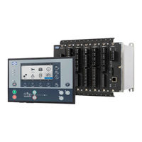
Deif PICUS PPM 300 Manual (213 pages)
Protection and Power Management
Brand:
Deif
| Category:
Power distribution unit
| Size: 4 MB
Table of Contents
Table of Contents
2
1 Introduction
8
About PICUS
8
Introduction to PICUS
8
About the PICUS Manual
8
General Purpose
8
Intended Users of the PICUS Manual
8
Where to Find or Configure Information
9
Software Versions
10
Technical Support
10
List of Technical Documentation for PPM 300
11
Warnings and Safety
12
Safety During Operation
12
Legal Information
13
Disclaimers
13
Open Source Software
13
Trademarks
13
Copyright
13
2 Getting Started with PICUS
14
Requirements
14
System Requirements
14
Download
14
Downloading PICUS
14
Installation
17
Installation Prerequisites
17
Install PICUS
17
Ethernet Connection
21
Connect Your Computer
21
Launch
22
Launching PICUS
22
PICUS Overview
22
Screen Layout
22
Regional Settings
24
About Information
25
Notifications
26
3 Connection
29
Introduction
29
Page Layout
30
Connect Page
30
Tasks
32
Log on to Controller(S)
32
Change Logged on User
33
Disconnect from Controller(S)
34
Open Offline Project
34
Connect Host
35
Connect All
36
Initial Download (Initial DL)
36
4 Date and Time
38
Introduction
38
Page Layout
38
Date and Time Page
38
Tasks
40
Configure Date and Time
40
5 Permissions
41
Introduction
41
Page Layouts
41
Groups Page
41
Users Page
43
Tasks
45
Configure Groups
45
Create a New Blank Group
45
Create a New Copied Group
46
Edit a Group
46
Delete a Group
47
Write Groups to the Controller
47
Broadcast Groups to Selected Controller(S)
47
Configure Users
49
Create a New Blank User
49
Create a New Copied User
50
Edit a User
50
Delete a User
50
Write Users to the Controller
50
Broadcast Users to Selected Controller(S)
51
6 Single-Line Diagram
53
Introduction
53
Components
53
Busbar Colours
59
Diagram Icons
59
Page Layout
60
Single-Line Page
60
Tasks
61
Configure the Single-Line Diagram
61
Add a Component
61
Configure a Component
62
Move a Component
62
Delete a Component
63
Create a Ring Busbar
63
Refresh the Single-Line Diagram
66
Clear and Reset the Single-Line Diagram
67
Broadcast the Single-Line Diagram
67
7 Input/Outputs
69
Introduction
69
Page Layout
70
Input/Output Page
70
Digital Input
72
Alarms Page
72
Functions Page
74
Digital Output
76
Relay Setup Page
76
Alarms Page
78
Function Page
79
Analogue Input
81
Introduction to Analogue Inputs
81
Functions Page
82
Sensor Setup Page
83
Alarms Page
86
Analogue Output
89
Introduction to Analogue Outputs
89
Function Page
89
Output Setup
90
Tasks
93
Configure the Terminal Name
93
Configure Custom Alarm(S)
93
Configure Function(S)
95
Configure the Relay Setup
95
Configure the Sensor Setup
97
Configure the Output Setup
99
8 Parameters
102
Introduction
102
Page Layout
104
Parameters Page
104
Tasks
105
Configure Parameters
105
9 Customlogic
108
Introduction
108
Ladder Logic
108
Customlogic Restrictions
109
Page Layout
110
Project Overview Page
110
Element Setup Page
112
Customlogic Elements
113
Element Overview
113
Function Blocks
115
Variables
116
Tasks
117
Overview
117
Create a Customlogic Project
117
Create a Logic Line with Customlogic Elements
118
Configure a Customlogic Element
119
Enable Customlogic
121
Customlogic State Output
121
View Active Logic
121
Basic Examples
122
Logical Functions
122
Example 1: External Light Activates When System Is in AUTO
126
Example 2: External Light Flashes When System Is under Switchboard Control
128
Advanced Examples
130
Example 1: Activate an External Component until Push-Button Is Pressed
130
Example 2: Basic Inter-Controller Communication
134
Example 3: Start Genset Engine
137
Example 4: Power Management Rules Dependent on Bus Tie Breaker Position
141
10 Live Data
145
Introduction
145
Views
145
Page Layout
149
Live Data Page
149
Tasks
150
View Live Data
150
11 Supervision
152
Introduction
152
Busbar Colours
152
Diagram Icons
152
Page Layout
153
Supervision Page
153
Tasks
154
Review Supervision
154
12 Alarms
155
Introduction
155
Page Layout
156
Alarms Page
156
Alarm Notification Window
157
Tasks
158
Review and Handle Alarms
158
View Alarm Details
158
Acknowledge an Unacknowledged Alarm
159
Reset All Latches
159
Shelve an Alarm
160
Unshelve an Alarm
161
Remove an Alarm from Service
161
Return an Alarm to Service
162
13 Log
163
Introduction
163
Page Layout
163
Log Page
163
Tasks
164
Review Log Entries
164
14 Emulation
166
Introduction
166
Enable Emulation
166
Busbar Colours
166
Diagram Icons
166
Page Layout
168
Emulation Input/Output Page
168
Emulation Emulator Page
169
Tasks
170
Configure Emulation Loads
170
Apply or Remove Emulation Load(S)
171
Simulate Input/Output
172
Emulator Options
173
15 Backups
174
Introduction
174
Backing up Information
174
Back up or Restore Restrictions
174
Page Layout
175
Backup Page
175
Restore Page
176
Tasks
177
Back up or Restore a Configuration
177
Create a Backup File
177
Restore or Broadcast from a Folder
178
Broadcast from the Connected Controller
182
16 Firmware
185
Introduction
185
Installation Prerequisites
185
Page Layout
186
Update Controller(S) Page
186
Update Display(S) Page
187
Tasks
189
Download PPM Firmware
189
Install Firmware
191
17 Report
192
Introduction
192
Page Layout
192
Report Page
192
Report Preview Page
193
Tasks
194
Create and Print Report
194
18 Troubleshooting
195
Connections
195
Unable to See any Controllers
195
Notifications
196
Notification Windows Not Displaying
196
Firmware
196
Firmware Update Issues
196
Files
197
Unable to Locate File(S)
197
Broadcast
198
Unsuccessful Broadcast Attempt(S)
198
19 Glossary
199
Terms and Abbreviations
199
Units
203
Symbols
204
Symbols for Notes
204
Menus and Icon Symbols
205
Single-Line Symbols
209
Supervision Symbols
210
Emulation Symbols
210
Customlogic Symbols
212
Advertisement
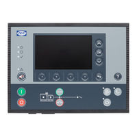
Deif PICUS PPM 300 Operator's Manual (157 pages)
Protection and Power Management
Brand:
Deif
| Category:
Control Systems
| Size: 4 MB
Table of Contents
Table of Contents
2
1 Introduction
7
About the Operator's Manual
7
Intended Users of the Operator's Manual
7
Software Versions
7
Technical Support
7
List of Technical Documentation for PPM 300
8
Warnings and Safety
9
Safety During Installation and Operation
9
Automatic and Remote-Controlled Starts
9
Switchboard Control
9
Controller Power Supply
10
Factory Settings
10
Electrostatic Discharge
10
Do Not Manually Override Active Alarm Actions
10
Legal Information
10
Third Party Equipment
10
Warranty
11
Open Source Software
11
Trademarks
11
Copyright
11
Disclaimer
11
2 Overview of the System
12
Overview
12
Operating the PPM 300 Controllers
12
Operator Messages
13
Controller Status Texts
13
Operator Information Messages
17
3 Controller Equipment
24
Display Unit
24
Introduction to the Display Unit
24
Display Unit Leds and Push-Buttons
25
GENSET Controller Leds and Push-Buttons
26
EMERGENCY Genset Controller Leds and Push-Buttons
28
SHAFT Generator Controller Leds and Push-Buttons
30
SHORE Connection Controller Leds and Push-Buttons
32
BUS TIE Breaker Controller Leds and Push-Buttons
33
Controller Rack
35
Rack Leds
35
PSM3.1 Leds
35
PCM3.1 Leds
36
4 Operating the System
37
Introduction
37
About the Operator Actions
37
GENSET Controller Basic Actions
37
Introduction to Operating the GENSET Controllers
37
Changing Modes
37
Starting the Genset
39
Stopping the Genset
39
Closing the Genset Breaker
40
Opening the Genset Breaker
40
Setting Genset Start and Stop Priority
41
EMERGENCY Genset Controller Basic Actions
41
Introduction to Operating the EMERGENCY Genset Controller
41
Changing Modes
41
Starting the Emergency Genset
43
Stopping the Emergency Genset
43
Closing the Emergency Genset Breaker
44
Opening the Emergency Genset Breaker
44
Closing the Tie Breaker
45
Opening the Tie Breaker
46
Emergency Genset Test Function
47
SHAFT Generator Controller Basic Actions
47
Introduction to Operating the SHAFT Generator Controller
47
Closing the Shaft Generator Breaker
48
Opening the Shaft Generator Breaker
49
SHORE Connection Controller Basic Actions
49
Introduction to Operating the SHORE Connection Controller
49
Closing the Shore Connection Breaker
50
Opening the Shore Connection Breaker
51
BUS TIE Breaker Controller Basic Actions
51
Introduction to Operating the BUS TIE Breaker Controller
51
Closing the Bus Tie Breaker
51
Opening the Bus Tie Breaker
52
5 Using the Display Unit
53
Introduction
53
About the Display Unit
53
About the Status Bar
53
About the Soft Keys
54
About the Virtual Keyboard
56
View Help
57
6 Log on
58
Permissions
58
About Permissions
58
Log on to Controller
58
Log off
59
Log off from Controller
59
Language
60
Change Language
60
Reset
61
Reset Display Unit
61
User Info
62
View User Information
62
7 Configure
63
Introduction
63
About Configure
63
Priority
63
View or Configure Priority
63
Counters
64
View or Configure Counters
64
Parameters
68
View or Configure Parameters
68
Input/Output
69
Configure Input/Output
69
Selecting a Hardware Module
69
View or Configure Hardware Module I/O Terminals
70
I/O Terminal Settings
71
Digital Input (DI)
72
Configure I/O Name
72
Configure Function(S)
73
Configure Alarm(S)
73
Digital Output (DO)
77
Configure I/O Name
77
View or Configure I/O Relay
77
Configure Function(S)
78
Configure Alarms
79
Analogue Input (AI)
80
Introduction to Analogue Inputs
80
Configure Analogue Input (AI)
81
Configure I/O Name
81
Configure Function(S)
82
Configure Alarm(S)
85
View or Configure Sensor
88
Analogue Output (AO) / Pulse Width Modulation (PWM)
100
Configure Analogue Output (AO)
100
Configure I/O Name
101
Configure Function
101
View or Configure Analogue Output (AO) or Pulse Width Modulation (PWM)
104
8 Alarm
117
Introduction
117
Alarm Indication
117
About the Alarm List
118
Alarm Symbols
118
Alarm Actions
120
Alarm Notification
120
Alarm Actions
121
View Alarms
121
Operator Actions
121
Silence Horn
122
Acknowledge Alarm(S)
122
Reset Latched Alarm(S)
123
Shelve Alarm(S)
123
Out of Service Alarm(S)
124
9 Live Data 9.1 Introduction
126
Live Data
126
View the Live Data
126
Live Data Counters
127
10 Tools
129
Introduction
129
About Tools
129
Communication
129
Configure Communication
129
Advanced
131
About Advanced
131
Brightness
132
About Brightness Menu
132
View or Configure Brightness Level Setting
132
View or Configure the Brightness Time Setting
133
Permissions
134
About Permissions
134
View Groups
134
View Users
135
Controller Type
136
Prerequisites
136
Change Controller Type
136
11 Log
139
Introduction
139
About the Log
139
Log Events
139
Log
140
Review Log Events
140
12 Info
141
Introduction
141
About Info
141
Production
141
View the Production Info
141
About
142
View about
142
13 Troubleshooting
143
Introduction
143
Finding the Source of the Problem
143
Using SWBD Control for Troubleshooting
143
Introduction to SWBD Control
143
Troubleshooting the System under SWBD Control
143
Troubleshooting Alarms
145
Troubleshooting Analogue Input Sensor Failures
145
Engine
145
Start Failure
145
Overspeed
146
Network and Communication
146
Ethernet Redundancy Broken
146
14 Maintenance
148
PCM3.1 Internal Battery
148
Changing the Battery
148
15 End-Of-Life
150
Disposal of WEEE
150
Disposal of Waste Electrical and Electronic Equipment
150
16 Glossary
151
Terms and Abbreviations
151
Units
154
Symbols
156
Symbols for Notes
156
Display Unit Symbols and Push-Buttons
156
Deif PICUS PPM 300 Installation Instructions Manual (144 pages)
Protection and Power Management
Brand:
Deif
| Category:
Controller
| Size: 2 MB
Table of Contents
Table of Contents
2
1 Introduction
7
About the Installation Instructions
7
General Purpose
7
Intended Users of the Installation Instructions
7
Technical Support
7
List of Technical Documentation for PPM 300
7
Warnings and Safety
9
Safety During Installation and Operation
9
Disable the Breakers
9
Disable the Engine Start
9
Metal Fragments and Other Objects
9
Electrostatic Discharge
9
Controller Power Supply
10
Connect the Controller Protective Earth
10
Switchboard Control
10
Factory Settings
10
Automatic and Remote-Controlled Starts
10
Data Security
10
Do Not Use Unsupported Hardware Modules
10
Legal Information
11
Third Party Equipment
11
Warranty
11
Open Source Software
11
Trademarks
11
Disclaimer
11
Copyright
11
2 Preparing for the Installation
12
Tools
12
Tools Required for Mounting and Installation
12
Materials
13
Materials Required
13
Site
14
Site Requirements
14
3 Mounting the Equipment
15
Introduction
15
Introduction to Mounting the Equipment
15
Mounting Modules
15
Rack Slots and Their Requirements
15
Mounting Hardware Modules in the Rack
16
Mounting the Controller Rack
17
Rack Dimensions
17
Rack Drilling Template
18
Mounting the Rack
19
Rack Cable Strain Relief
22
Mounting the Display Unit
24
Display Unit Dimensions
24
Display Unit Panel Cutout
24
Mounting the Display Unit
25
Display Unit Cable Strain Relief
27
4 Default Wiring for Controller Types
29
Introduction
29
Introduction to Default Wiring
29
Hardware Configuration
30
PSM3.1 Terminal Connections and Default Wiring
31
PSM3.1 Terminal Connections
31
Default Wiring for Controller PSM3.1
32
ACM3.1 Terminal Connections and Default Wiring
32
ACM3.1 Terminal Connections
32
Mounting Voltage Encoding Pins
34
Default Wiring for GENSET Controller ACM3.1
36
Default Wiring for EMERGENCY Genset Controller ACM3.1
37
Default Wiring for SHAFT Generator Controller ACM3.1
38
Default Wiring for SHORE Connection Controller ACM3.1
39
Default Wiring for BUS TIE Breaker Controller ACM3.1
40
PCM3.1 Terminal Connections and Default Wiring
41
PCM3.1 Terminal Connections
41
PCM3.1 Ethernet Connections
41
5 Default Wiring for the Optional Modules
43
IOM3.1 Terminal Connections and Default Wiring
43
IOM3.1 Terminal Connections
43
Default Wiring for GENSET Controller IOM3.1
45
Default Wiring for EMERGENCY Genset Controller IOM3.1
46
Default Wiring for SHAFT Generator Controller IOM3.1
47
Default Wiring for SHORE Connection Controller IOM3.1
48
Default Wiring for BUS TIE Breaker Controller IOM3.1
49
IOM3.4 Terminal Connections and Default Wiring
50
IOM3.4 Terminal Connections
50
Default Wiring for Input/Output Module IOM3.4
50
EIM3.1 Terminal Connections and Default Wiring
51
EIM3.1 Terminal Connections
51
Default Wiring for GENSET Controller EIM3.1
52
Default Wiring for EMERGENCY Genset Controller EIM3.1
53
GAM3.1 Terminal Connections and Default Wiring
54
GAM3.1 Terminal Connections
54
Default Wiring for GAM3.1
55
Default Wiring for EMERGENCY Genset Controller GAM3.1
56
GAM3.2 Terminal Connections and Default Wiring
56
GAM3.2 Terminal Connections
56
Default Wiring for GAM3.2
58
6 Wiring the Controller Hardware Modules
59
Introduction
59
Power Supply Module PSM3.1
59
PSM3.1 Terminal Overview
59
Frame Ground Wiring
59
Power Supply Wiring
60
Relay Output Wiring
61
Internal Communication Connections
62
Alternating Current Module ACM3.1
63
ACM3.1 Terminal Overview
63
Voltage Measurements Wiring
63
Current Measurements Wiring
63
Input Output Module IOM3.1
64
IOM3.1 Terminal Overview
64
Relay Output Wiring
65
Digital Inputs Wiring
66
Input/Output Module IOM3.4
70
IOM3.4 Terminal Overview
70
Transistor Output Wiring
71
Digital Inputs Wiring
71
Engine Interface Module EIM3.1
75
EIM3.1 Terminal Overview
75
Frame Ground Wiring
76
Power Supply Wiring
76
Relay Output Wiring
78
Relay Output with Wire Break Detection
78
Digital Inputs Wiring
81
Magnetic Pickup Unit (MPU) Input Wiring
85
W Input Wiring
85
Analogue Current or Resistance Inputs Wiring
87
Governor and AVR Module GAM3.1
91
GAM3.1 Terminal Overview
91
Relay Output Wiring
92
Load Sharing Wiring
93
Analogue Current or Voltage Outputs Wiring
93
Pulse Width Modulation (PWM) Output Wiring
94
Analogue Current or Voltage Input Wiring
94
Governor and AVR Module GAM3.2
95
GAM3.2 Terminal Overview
95
Frame Ground Wiring
96
Power Supply Wiring
96
Analogue Current or Voltage Outputs Wiring
98
Pulse Width Modulation (PWM) Output Wiring
99
Digital Inputs Wiring
99
Relay Output Wiring
103
Processor and Communication Module PCM3.1
104
PCM3.1 Terminal Overview
104
CAN Bus Communication Wiring
105
Ethernet Connections
105
7 Wiring Examples for Controller Functions
107
Introduction
107
AC Measurement Wiring
107
System AC Configuration
107
Source] AC Configuration
111
Busbar] AC Configuration
112
Breaker Wiring
114
Pulse Breaker
114
Continuous Breaker
114
Compact Breaker
115
External Breaker
116
Redundant Breaker Feedback
117
Regulation
117
Using a Current Output for Voltage Regulation
117
Power Management Wiring
118
Heavy Consumer
118
8 Wiring the Communication
121
DEIF Ethernet Network Communication
121
Communication
121
Connecting the Communication
121
Topology Restrictions
125
Topology Examples
126
9 Wiring the Display Unit
129
Display Unit Overview and Wiring
129
Display Unit Terminal Overview
129
Frame Ground Wiring
130
Power Supply Wiring
130
Relay Output Wiring
131
Ethernet Connections
132
10 Multi-Line 300 as a Safety System
133
Fast Over-Current Protection (ANSI 50/50TD)
133
Introduction to Safety System for ANSI 50/50TD
133
Current Transformer Requirements
133
Power Supply Requirements
133
Function Requirements
133
Parameter Requirements
134
11 Glossary
135
Terms and Abbreviations
135
Units
139
Symbols
140
Symbols for Notes
140
Controller and Component Symbols
140
Drawing Symbols
141
Advertisement
Advertisement
Related Products
Deif PPM-3
Deif PPM
Deif PPM 300
Deif PPU-3
Deif PPU
Deif PPU 300
Deif PPU-2
Deif 4189340315C
Deif AGC 100
Deif AGC 150
Deif Categories
Controller
Measuring Instruments
Control Unit
Monitor
Control Systems
More Deif Manuals
Login
Sign In
OR
Sign in with Facebook
Sign in with Google
Upload manual
Upload from disk
Upload from URL