Table of Contents
Advertisement
Quick Links
Advertisement
Table of Contents

Related Manuals for Titon aura-t TP536/EU


Summary of Contents for Titon aura-t TP536/EU
- Page 1 aura-t TP536/EU Product Manual HRV controller ventilation systems...
-
Page 2: Important Information
Warnings, Safety information and Guidance Important Information Read instructions fully before the installing this appliance. 1. This manual covers the operation of the HRV control sys- tem only, it must therefore be read in conjunction with the relevant heat recovery unit Product Manual. 2. - Page 3 8. The appliance is not suitable for installation to the exterior of the dwelling. 9. This appliance can be used by children aged from 8 years and above and persons with reduced physical, sensory or mental capabilities or lack of experience and knowledge if they have been given supervision or instruction concern- ing use of the appliance in a safe way and understand the hazards involved.
-
Page 4: Table Of Contents
Contents Warnings, Safety information and Guidance Installation Important Information ......2 Location ........12 Fixing. -
Page 5: Product Overview
The aura-t is a programmable touch screen controller which monitors and displays the status of a Titon ECOaura HRV unit. It allows the unit to be commissioned, and gives the user both manual and timed control of fan speeds. The aura-t is connected to the HRV via a low voltage connection and can be sited remotely from the unit. -
Page 6: Features
Features The following gives an outline description for each of the product features. Speed Selection & Display Programmable Speeds The unit speed can be manually selected The unit has 4 programmable speed via the on screen 1, 2, 3 & 4 buttons/ settings, all speeds are variable between icons which are also used to display any 14-100% and allow independent speed... -
Page 7: User Interface
User Interface The aura-t is operated via a LCD touchscreen. The screen is backlit, the backlight operates when the screen is touched. Menu Tabs The aura-t screen has three interactive menu screens which are selected via tabs at the bottom of the touchscreen. Passcode Screen Function Monitor &... -
Page 8: Run Mode
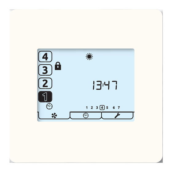
Run Mode The aura-t controls the HRV unit’s 4 programmable speed settings. This is the Run Mode screen; use the number buttons to select the required fan speed. Press and Hold the [1] button to turn the unit o , just the [1] icon will be displayed;... -
Page 9: Other Icons
Other Icons Other status icon that may be visible on the screen are listed below: The lters need changing or cleaning, refer to the Settings Menu for details of how to reset the timer. Frost Protection, if this icon is constantly lit the temperature outside is low and the speed of the HRV Supply Fan has been reduced to prevent damage to the Heat Cell. -
Page 10: Timer Mode
Timer Mode The controller has a seven day, four events per day timer. The timer is used to automatically change the HRV speed to Setback, Speed 1 at programmed times. An additional function of the timer is that when it activates Setback there is an option to engage Boost Inhibit. - Page 11 Timer Setup , Tap this button to adjust the Timer, see Timer Setup section. Tap this to Exit and return to Run Mode. When the timer has automatically switched the HRV to Speed 1 ƒ this can be manually overridden by tapping [2-4] keys. Tap the Speed 1 key to return to timer control.
-
Page 12: Installation
Installation Location The aura-t should be mounted in position convenient for the householder and where the supplied control cable will reach. Fixing Un-clip the front of the aura-t case from the Back Plate. Thread the control cable through the hole in the Back Plate. Fixing Holes Wiring Access Hole Connection to HRV... -
Page 13: Wiring
Wiring The aura-t’s control cable may be supplied tted with a plug in connector for connection to the HRV, if the HRV does not have a socket remove the plug and use the wiring diagrams below. Connection to HRV Connection to aura-t... -
Page 14: Fan Commission
Fan Commission Fan Commission Mode is entered by pressing the Fan Button for 5 seconds whilst in Run Mode. A ashing item on the screen indicates it is being edited. Select the required fan speed using the number buttons at the left of the screen. -
Page 15: Timer Setup
Timer Setup Timer setup is achieved in three steps 1 Day Selection Tap the Timer Mode tab to enter the Timer Mode menu. Tap the Timer Setup Key to commence setup. A ring around the day selected will blink. Change the day that the timers are to be edited by using the Arrow Keys. - Page 16 2 Select Event & Edit Timers In this example; tapping the Save key will save the settings; these will set the unit to run at Speed 1 between 08:00 & 12:00 Tap the event number to be edited [1-4] from on left hand side of the screen.
- Page 17 3 Copy Timers or Exit Timer Setup The ashing Copy icon indicates the option to copy just edited settings to another day. Tap the Enter Key to commence copy procedure. Tap the Exit key to start editing another day’s times or press a second time to exit to Run Mode.
-
Page 18: Timer Defaults
Timer Defaults Event timings: The Speed 2 cannot be set earlier than Speed 1. ƒ Events where Speed 1 and Speed 2 are identical are ignored by the timer. ƒ Event Days Speed 1 Speed 2 00:00 06:30 08:30 12:00 13:30 18:00 22:30... -
Page 20: Controller Setup
Controller Setup Enter key. Exit Key. Tap the Setup Mode tab to enter the Setup Mode menu. All the editable settings in the Controller Setup menu are accessed in the same way. Menu navigation is achieved by rst Setting Selection and then Editing. Setting Selection Arrow keys are used to select a setting, the setting will ash. - Page 21 Humidity threshold Kitchen Overrun timer. Wet room Overrun timer. Summer Bypass Setup. Passcode Disable / Enable. Filter Reset If a lter change is required the reset ring will be ashing. Tap the Enter key to reset or the Exit key. If a lter change is not due but the lter timer requires resetting press the Enter key twice.
-
Page 22: Summer Bypass Setup
Summer Bypass Setup Use to adjust value up or down. Enter key. Use the Supply and Extract buttons to select which threshold is to be adjusted. Supply represents from atmosphere air temperature; Supply Extract represents from dwelling air temperature. Extract Tap button[4] to enable / disable SUMMERboost. -
Page 23: Switch Setup Menu
Switch Setup Menu In this Sub-Menu of the Setup Menu the installer can con gure the function of the HRV unit’s switch inputs S1, S2, S3, LS1 & LS2 (see HRV Product Manual for details) Enter key. Exit Key. Press and Hold the Setup Mode tab to enter the Switch Setup Mode menu.* Switch Setup menu active. -
Page 24: Maintenance
Maintenance The aura-t is maintenance free. Cleaning Exterior For best results use a clean damp micro bre cloth. Do not use abrasive cleaners, waxes, solvents or alcohol based cleaning products; do not use paper towels for cleaning the aura-t. Appendix aura-t Con gurable Defaults The table below details the default values and the range of available settings, plus any additional information about those settings the aura-t can con gure. - Page 25 Live Switch options are: Kitchen Boost, Wetroom Boost. Live Switches also use the Boost overrun and delay times for the rooms they have been con gured to. Some control features documented in this manual may not be compatible with older Titon HRV units.
-
Page 26: Hrv Ecoaura Defaults
The table below details HRV settings and defaults, which that the aura-t CANNOT con gure. During installation and commissioning they may be changed from the default values by an alternate Titon controller. There is space available in the table where the installer should record con guration settings. - Page 27 Con gurable Item Range Default Con gured Room Sensor 1 Enable/Disable Enabled Disabled Disabled Sensor Type Lower threshold Upper threshold Room Sensor 2 Enable/Disable Enabled Disabled Disabled Sensor Type Lower threshold 800PPM Upper threshold 1400PPM If tted, Room Sensors are used to provide Demand Control Ventilation based on the environmental parameter they are measuring. Below their lower threshold they have no e ect on the ventilation rate;...
- Page 28 This Product Manual must be kept in the Home Information Pack. Installed by: MARKETING DIVISION 894 The Crescent, Colchester Business Park, Colchester, Essex, CO4 9YQ United Kingdom Tel: +44 (0) 1206 713800 Fax: +44 (0) 1206 543126 Email: ventsales@titon.co.uk Web: www.titon.com ©2017 TITON DO 5546 Iss 01...
Need help?
Do you have a question about the aura-t TP536/EU and is the answer not in the manual?
Questions and answers