Advertisement
Quick Links
sauder.com
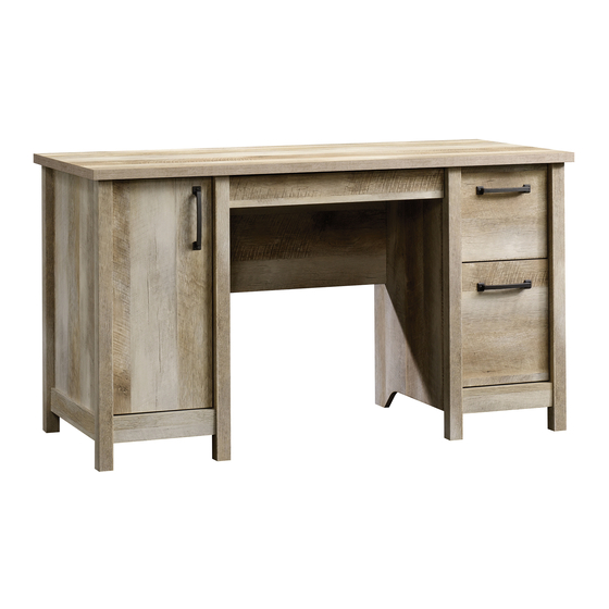
Computer Desk
Cannery Bridge Collection | Model 418326
Need help? Visit Sauder.com to view video assembly tips or chat with a live rep.
Prefer the phone? Call 1-800-523-3987.
Share your journey!
Sit and surf.
NOTE: THIS INSTRUCTION
BOOKLET CONTAINS IMPORTANT
SAFETY INFORMATION.
PLEASE READ AND KEEP FOR
FUTURE REFERENCE.
English pg 1-31
Français pg 32-35
Español pg 36-40
Lot # 366853
12/03/14
Purchased: __________________
Be sure to give us a ring before
making any returns. 1-800-523-3987
Advertisement

Related Manuals for Sauder Cannery Bridge 418326


Summary of Contents for Sauder Cannery Bridge 418326
- Page 1 Cannery Bridge Collection | Model 418326 NOTE: THIS INSTRUCTION BOOKLET CONTAINS IMPORTANT SAFETY INFORMATION. Need help? Visit Sauder.com to view video assembly tips or chat with a live rep. PLEASE READ AND KEEP FOR FUTURE REFERENCE. Prefer the phone? Call 1-800-523-3987.
- Page 2 DRAWER BRACE (1) PENCIL DRAWER BOX D469 FRONT (1) DOOR (1) PENCIL DRAWER BOTTOM (1) D702 DRAWER BOTTOM (1) ADJUSTABLE SHELF (1) DRAWER RIGHT SIDE (1) D954 FILE DRAWER BOTTOM (1) FRONT LEG (4) DRAWER LEFT SIDE (1) Page 2 418326 www.sauder.com/services...
- Page 3 Now you know Part Identifi cation our ABCs. D150 D702 D266 D468 D469 D267 D151 D954 www.sauder.com/services 418326 Page 3...
- Page 4 CAM DOWEL - 18 14H HINGE - 2 CAM SCREW - 12 WOOD DOWEL - 4 DOOR STOP - 1 101K RUBBER SLEEVE - 4 NAIL - 30 METAL PIN - 4 PULL - 3 CORD CLIP - 1 Page 4 418326 www.sauder.com/services...
- Page 5 15S SILVER 5/8" MACHINE SCREW - 6 BLACK 7/8" LARGE HEAD SCREW - 2 30S BLACK 1-9/16" FLAT HEAD SCREW - 14 BLACK 9/16" FLAT HEAD SCREW - 4 100S BLACK 2-3/4" FLAT HEAD SCREW - 6 www.sauder.com/services 418326 Page 5...
- Page 6 Look for this icon. It means a Step 1 video assembly tip is available at www.sauder.com/services/tips Assemble your unit on a carpeted fl oor or on the empty å carton to avoid scratching your unit or the fl oor. Push thirty HIDDEN CAMS (1F) into the ENDS (A and B), å...
- Page 7 å Insert four WOOD DOWELS (15F) into the holes in the å FRONT LEGS (L). (12 used) 3 used in each leg These holes are closer to these edges. These holes are closer to these edges. www.sauder.com/services 418326 Page 7...
- Page 8 ENDS and UPRIGHTS. These surfaces should be even. These ends should be even. These surfaces should be even. These ends should be even. These surfaces should be even. These ends should be even. These surfaces should be even. Page 8 418326 www.sauder.com/services...
- Page 9 These edges Shoulder should be even. Apply pressure with your hands as you guide the MOLDINGS over the SCREWS and onto the ENDS. BLACK 9/16" FLAT HEAD SCREW (4 used in this step) www.sauder.com/services 418326 Page 9...
- Page 10 Step Step 5 Fasten the BACK LEGS (M) to the ENDS (A and B). Use å six BLACK 2-3/4" FLAT HEAD SCREWS (100S). 100S BLACK 2-3/4" FLAT HEAD SCREW (6 used in this step) Page 10 418326 www.sauder.com/services...
- Page 11 CABINET LEFT (45BB) to the RIGHT UPRIGHT (C). Use four GOLD 5/16" FLAT HEAD SCREWS (3S) through holes #1 and #4. GOLD 5/16" FLAT HEAD SCREW (4 used in this step) Roller end Roller end www.sauder.com/services 418326 Page 11...
- Page 12 CABINET LEFT (40CB) to the RIGHT UPRIGHT (C). Use four GOLD 5/16" FLAT HEAD SCREWS (3S) through holes #1 and #3. GOLD 5/16" FLAT HEAD SCREW (4 used in this step) Roller end Roller end Page 12 418326 www.sauder.com/services...
- Page 13 HEAD SCREWS (3S) through holes #1 and #3. GOLD 5/16" FLAT HEAD SCREW (4 used for the RAILS) Roller end Finished edge Finished BLACK 1-1/8" PAN HEAD SCREW surface (4 used for the EXTENSION BLOCKS) Roller end Finished edge www.sauder.com/services 418326 Page 13...
- Page 14 Tighten Risk of damage or Arrow injury. HIDDEN CAMS must be completely Arrow Maximum tightened. HIDDEN 210 degrees CAMS that are not completely tightened may loosen, and parts may separate. To Minimum completely tighten: 190 degrees Page 14 418326 www.sauder.com/services...
- Page 15 (4 used in this step) i t h o f a c S u r D E N H I D i t h f a c S u r D E N H I D www.sauder.com/services 418326 Page 15...
- Page 16 Push the DOOR STOP (4I) into the hole in the TOP (E). å Maximum Arrow Fasten the BOTTOMS (F) to the UPRIGHTS (C and D). å 210 degrees Tighten four HIDDEN CAMS. Minimum 190 degrees Notched edge Notched edge Page 16 418326 www.sauder.com/services...
- Page 17 Step Step 12 Slide the BOTTOM MOLDINGS (Q) onto the notched å edges of the BOTTOMS (F). *U.S. Patent No. 5,499,886 å Notched edge Slide the BOTTOM MOLDINGS (Q) onto the notched edges. www.sauder.com/services 418326 Page 17...
- Page 18 210 degrees Minimum 190 degrees f a c S u r w i t h D E N H I D i t h o f a c S u r D E N H I D Page 18 418326 www.sauder.com/services...
- Page 19 BOTTOMS (F). Do not put NAILS in these two holes. Edge without holes The edge of the BACK should be even with the edge of the UPRIGHT. These holes should line up over the LEG. www.sauder.com/services 418326 Page 19...
- Page 20 Step Step 15 Fasten two HINGES (14H) to the DOOR (J). Use four å BLACK 1/2" FLAT HEAD SCREWS (11S). BLACK 1/2" FLAT HEAD SCREW (4 used in this step) Page 20 418326 www.sauder.com/services...
- Page 21 Fasten a PULL (101K) to the DOOR (J). Use two SILVER å 5/8" MACHINE SCREWS (15S). Mounting See the next step for DOOR adjustments. screw å Hinge 101K SILVER 5/8" MACHINE SCREW (2 used for the PULL) www.sauder.com/services 418326 Page 21...
- Page 22 To adjust the DOORS in or out (depth), loosen the mounting å screw one turn and move the DOORS in or out, as needed. Tighten the mounting screw after making adjustments. Mounting screw (depth) Adjusting screw (horizontal) (vertical adjustment) Page 22 418326 www.sauder.com/services...
- Page 23 Fasten the DRAWER BRACE (EE) to the PENCIL å å DRAWER SIDES (D266 and D267). Use two BLACK DRAWER BACK (D468) and PENCIL DRAWER 1-9/16" FLAT HEAD SCREWS (30S). BOX FRONT (D469). Use two BLACK 1-9/16" FLAT HEAD SCREWS (30S). www.sauder.com/services 418326 Page 23...
- Page 24 Roller end BLACK 7/8" LARGE HEAD SCREW (2 used in this step) D267 Roller end D469 r f a D266 w i t l e s GOLD 5/16" FLAT HEAD SCREW (4 used in this step) Page 24 418326 www.sauder.com/services...
- Page 25 D29). Use four BLACK 1-9/16" FLAT HEAD SCREWS (30S). NOTE: Be sure the FILE DRAWER BOTTOM (D954) inserts into the å groove of the FILE DRAWER BACK (D151). Repeat this step for the remaining drawer using parts N, D26, D27, D150, å and D702. www.sauder.com/services 418326 Page 25...
- Page 26 å hole in the SLIDE. Roller end Screw head - turn CAM to line up holes in the SLIDES with holes in DRAWER SIDES Roller end GOLD 5/16" FLAT HEAD SCREW (4 used in this step) Page 26 418326 www.sauder.com/services...
- Page 27 SLIDE. Roller end Screw head - turn CAM to line up holes in the SLIDES with holes in DRAWER SIDES Roller end GOLD 5/16" FLAT HEAD SCREW (4 used in this step) www.sauder.com/services 418326 Page 27...
- Page 28 å two SILVER 5/8" MACHINE SCREWS (15S). Fasten a PULL (101K) to the FILE DRAWER FRONT (O). å Use two SILVER 5/8" MACHINE SCREWS (15S). SILVER 5/8" MACHINE SCREW (4 used for the PULLS) 101K 101K Page 28 418326 www.sauder.com/services...
- Page 29 FILE RODS (7B), then press this FILE GLIDE over the FILE DRAWER LEFT SIDE (D29). Insert the FILE RODS into the holes of your choice in the FILE GLIDES, depending on your fi le sizes. www.sauder.com/services 418326 Page 29...
- Page 30 Lift the front of the drawer up and slide it into the unit. Repeat this step to insert the PENCIL DRAWER. 25 lbs. 70 lbs. 40 lbs. 10 lbs. 15 lbs. (4 used) 25 lbs. Page 30 418326 www.sauder.com/services...
- Page 31 #4. The higher the screw in the oblong hole, the higher your drawer front will be. The lower the screw, the lower the drawer front. www.sauder.com/services 418326 Page 31...
- Page 32 EXTRÉMITÉ DROITE ................1 40CA ÉLÉMENT DROITE ................2 pour future référence. EXTRÉMITÉ GAUCHE ................ 1 40CB ÉLÉMENT GAUCHE ................2 Pour contacter Sauder MONTANT DROIT ................. 1 40CC TIROIR DROIT ..................2 en ce qui concerne cet MONTANT GAUCHE ................1 40CD TIROIR GAUCHE ...................2 élément, faire référence...
- Page 33 Fixer les PIEDS ARRIÈRE (M) aux EXTRÉMITÉS (A et B). Utiliser six ÉTAPE 11 VIS TÊTE PLATE 70 mm NOIRES (100S). Enfoncer l'ARRÊT DE PORTE (4I) dans le trou du DESSUS (E). Fixer les DESSOUS (F) aux MONTANTS (C et D). Serrer quatre EXCENTRIQUES ESCAMOTABLES. www.sauder.com/services 418326 Page 33...
- Page 34 Fixer le DEVANT DE TIROIR À CRAYONS (P) au DEVANT DE MÉTAUX 16 mm ARGENTÉES (15S). CAISSON DE TIROIR À CRAYONS (D469). Utiliser deux VIS TÊTE Voir l'étape suivante pour réglages des PORTES. LARGE 22 mm NOIRES (17S). Page 34 418326 www.sauder.com/services...
- Page 35 à travers le trou fendu dans la COULISSE. sécurité fi gurant sur les pages arrière du manuel d’instructions. Ceci complète l'assemblage. Nettoyer à l’ a ide d’une encaustique pour meubles ou d’un chiff on humide. Essuyer. www.sauder.com/services 418326 Page 35...
- Page 36 EXTREMO IZQUIERDO ..................1 40CB GABINETE IZQUIERDO ..............2 pour future référence. PARAL DERECHO ....................1 40CC CAJÓN DERECHO ................2 Pour contacter Sauder PARAL IZQUIERDO .....................1 40CD CAJÓN IZQUIERDO................2 en ce qui concerne cet PANEL SUPERIOR ....................1 45BA GABINETE DERECHO ................ 1 élément, faire référence...
- Page 37 Escondidos que no se aprieten completamente se afl ojarán y las y B). Alinee las ranuras de las MOLDURAS sobre las cabezas de los partes pueden separarse. Para apretar completamente, atornille el TORNILLOS de los EXTREMOS. excéntrico escondido 210 grados. www.sauder.com/services 418326 Page 37...
- Page 38 BISAGRAS. Debe apretar cada TORNILLO unas vueltas antes de apretar cualquier tornillo fi rmemente. Fije un TIRADOR (101K) a la PUERTA (J). Utilice dos TORNILLOS PLATEADOS PARA METAL de 16 mm (15S). Consulte el próximo paso para ajustar la PUERTA. Page 38 418326 www.sauder.com/services...
- Page 39 NOTA: Utilice los agujeros correspondientes indicados en los LADOS DE CAJÓN. Fije la CARA DE CAJÓN PARA LÁPICES (P) al FRENTE DE CAJÓN PARA LÁPICES (D469). Utilice dos TORNILLOS NEGROS DE CABEZA GRANDE de 22 mm (17S). www.sauder.com/services 418326 Page 39...
- Page 40 NOTA: Por favor, lea las páginas de atrás del folleto de instrucciones en cuanto a importante información de seguridad. Esto completa el ensamblaje. Limpie con su pulimento para muebles preferido o un paño húmedo. Seque con un paño. Page 40 418326 www.sauder.com/services...
- Page 41 à Les téléviseurs peuvent être particulièrement un téléviseur. cet eff et. lourds. De plus, le poids et l’emplacement du tube image ont tendance à rendre les téléviseurs instables et enclins à tomber vers l’ a vant. www.sauder.com/services 418326 Page 41...
- Page 42 Además, el peso y la ubicación del tubo de imagen tienden a causar la inestabilidad de televisores y propensa a volcarse hacia adelante. Page 42 418326 www.sauder.com/services...
- Page 43 GARANTIE LIMITÉE DE 5 ANS 1. Sauder Woodworking Co. (Sauder®) off re une couverture de garantie limitée à l’ a cheteur 4. La présente garantie ne s’ a pplique qu’ a ux défauts garantis qui se produisent pour initial du présent produit pendant une période de cinq ans à...
- Page 44 Dear Valued Customer: So, how did it go? Thanks so much for choosing Sauder® furniture. I hope the Set a world record for speed? purchase and assembly process was a positive experience Feeling good about yourself? and you feel good about the furniture you just built. If you Nice.
Need help?
Do you have a question about the Cannery Bridge 418326 and is the answer not in the manual?
Questions and answers