Advertisement
Quick Links
sauder.com
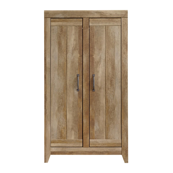
Storage Cabinet
Adept Storage Collection | 418141
Need help? Visit Sauder.com to view video assembly tips or chat with a live rep.
Prefer the phone? Call 1-800-523-3987.
Share your journey!
Store behind
closed doors.
NOTE: THIS INSTRUCTION
BOOKLET CONTAINS IMPORTANT
SAFETY INFORMATION.
PLEASE READ AND KEEP FOR
FUTURE REFERENCE.
English pg 1-32
Français pg 33-36
Español pg 37-40
Lot # 366939
11/20/15
Purchased: __________________
Be sure to give us a ring before
making any returns. 1-800-523-3987
Advertisement

Related Manuals for Sauder Adept Storage 418141


Summary of Contents for Sauder Adept Storage 418141
- Page 1 Adept Storage Collection | 418141 NOTE: THIS INSTRUCTION BOOKLET CONTAINS IMPORTANT SAFETY INFORMATION. Need help? Visit Sauder.com to view video assembly tips or chat with a live rep. PLEASE READ AND KEEP FOR FUTURE REFERENCE. Prefer the phone? Call 1-800-523-3987.
- Page 2 Assembly Tools Required Part Identifi cation No. 2 Phillips Screwdriver Tip Shown Actual Size Hardware Identifi cation Assembly Steps 5-32 Hammer Not actual size Français 33-36 Español 37-40 Skip the power trip. Safety 41-42 This time. Warranty Page 2 418141 www.sauder.com/services...
- Page 3 BACK (1) TOP MOLDING (1) LEFT END (1) DOOR (2) DOOR MOLDING (4) UPRIGHT (1) ADJUSTABLE SHELF (6) CENTER MOLDING (1) HINGE UPRIGHT (2) RIGHT LEG (1) TOP (1) LEFT LEG (1) BOTTOM (1) BASE (1) www.sauder.com/services 418141 Page 3...
-
Page 4: Table Of Contents
METAL PIN - 24 RUBBER SLEEVE - 24 CAM COVER - 24 BLACK 9/16" LARGE HEAD SCREW - 21 BLACK 1-7/8" FLAT HEAD SCREW - 9 SILVER 5/8" FLAT HEAD SCREW - 12 SILVER 3/8" MACHINE SCREW - 4 Page 4 418141 www.sauder.com/services... - Page 5 STEPS 1-11, 16-19, 24-27 Scan this QR code or go to this address: Scan this QR code or go to this address: Scan this QR code or go to this address: http://qr.sauder.com/?ID=1349 http://qr.sauder.com/?ID=1350 http://qr.sauder.com/?ID=1351 to watch a video on how to assemble...
- Page 6 Look for this icon. It means a Step 1 video assembly tip is available at www.sauder.com/services/tips Assemble your unit on a carpeted fl oor or on the empty å carton to avoid scratching your unit or the fl oor. Push eight SMALL HIDDEN CAMS (29F) into the holes in å...
- Page 7 DOWELS (26F) into the holes. Wipe away the excess GLUE. Righty tighty. Lefty loosey. Turn two CAM SCREWS (8F) into the DOOR MOLDING (N). å Repeat this step for the remaining DOOR MOLDINGS. å (8 used) (8 used) www.sauder.com/services 418141 Page 7...
- Page 8 NOTE: Be sure all angled edges on the DOOR MOLDINGS (N) å are facing the fl oor as shown in the enlarged diagram. 2-4. Repeat this step gluing and fastening the remaining DOOR å MOLDINGS (N) to the DOORS (H). Angled edge Page 8 418141 www.sauder.com/services...
- Page 9 Place the HINGE SPACERS (22H) over the large holes in å the DOORS (H). Fasten the HINGES (14H) to the DOORS (H). Use twelve å SILVER 5/8" FLAT HEAD SCREWS (23S). SILVER 5/8" FLAT HEAD SCREW (12 used in this step) www.sauder.com/services 418141 Page 9...
- Page 10 Insert the metal end of the CAM DOWEL into the HIDDEN CAM. Do not insert CAM DOWELS into these parts. Arrow Hole The arrow in the HIDDEN CAM must point toward the hole in the edge of the board. Page 10 418141 www.sauder.com/services...
- Page 11 B), TOP (E) and BOTTOM (F). Use seven BLACK 9/16" LARGE HEAD SCREWS (1S). NOTE: Be sure the BRACKETS are even with the long å edges of ENDS, TOP, and BOTTOM. BLACK 9/16" LARGE HEAD SCREW (7 used for the METAL BRACKETS) www.sauder.com/services 418141 Page 11...
-
Page 12: Hidden Cam
Tighten Risk of damage or Arrow injury. HIDDEN CAMS must be completely Arrow Maximum tightened. HIDDEN 210 degrees CAMS that are not completely tightened may loosen, and parts may separate. To Minimum completely tighten: 190 degrees Page 12 418141 www.sauder.com/services... - Page 13 Use four BLACK 1-7/8" FLAT HEAD SCREWS (2S). D E N H I D i t h f a c S u r The CAMS should be close to the fl oor. BLACK 1-7/8" FLAT HEAD SCREW (4 used in this step) www.sauder.com/services 418141 Page 13...
- Page 14 Fasten the LEFT END (B) to TOP (E) and BOTTOM (F). å Tighten four HIDDEN CAMS. Maximum Arrow 210 degrees Minimum 190 degrees i t h o f a c S u r D E N H I D Curved edge Page 14 418141 www.sauder.com/services...
-
Page 15: Black 9/16" Large Head Screw
BLACK 9/16" LARGE HEAD SCREW Fasten the BASE (L) to the BOTTOM (F). Use three BLACK å (9 used in this step) 9/16" LARGE HEAD SCREWS (1S). Do not completely tighten these screws at this time. www.sauder.com/services 418141 Page 15... - Page 16 NOTE: Be sure to tap NAILS into the holes that line up å over the UPRIGHT (C). Caution Do not stand the unit upright without the BACK fastened. The unit may collapse. These holes must line up over the UPRIGHT (C). NAIL (66 used in this step) Page 16 418141 www.sauder.com/services...
- Page 17 Turn twenty CAM SCREWS (8F) into the LEGS (J and K) å and CENTER MOLDING (O). BLACK 9/16" LARGE HEAD SCREW (2 used in this step) (20 used) Use the small holes for the DOOR STOPS (3G). Use the center holes only for the CAM SCREWS. www.sauder.com/services 418141 Page 17...
-
Page 18: Door Stop
STOPS with the RUBBER SLEEVES must be here. Be sure the top surface of the BASE and BOTTOM are even. Tighten three SCREWS in the BASE. BLACK 9/16" LARGE HEAD SCREW (2 used for the TIE PLATES) Page 18 418141 www.sauder.com/services... - Page 19 LEFT HINGE UPRIGHT (D) Arrow RIGHT HINGE UPRIGHT (D) Arrow Hole (8 used) The arrow in the HIDDEN CAM must point toward the hole in the edge of the board. www.sauder.com/services 418141 Page 19...
-
Page 20: Black 1-7/8" Flat Head Screw
Fasten the HINGE UPRIGHTS (D) to the TOP (E) and BOTTOM (F). å Use four BLACK 1-7/8" FLAT HEAD SCREWS (2S). Locator hole Locator hole LEFT HINGE UPRIGHT (D) RIGHT HINGE UPRIGHT (D) BLACK 1-7/8" FLAT HEAD SCREW (4 used in this step) Page 20 418141 www.sauder.com/services... - Page 21 Turn twenty CAM SCREWS (8F) into the LEGS (J and K) å and CENTER MOLDING (O). Use the exact holes shown. BLACK 9/16" LARGE HEAD SCREW (2 used for the DOOR STOPS) Use the small hole for (20 used) the DOOR STOP (3G). www.sauder.com/services 418141 Page 21...
-
Page 22: Rubber Sleeve
The DOOR STOPS with the RUBBER SLEEVES must be here. Be sure the top surface of the BASE and BOTTOM are even. Tighten three SCREWS in the BASE. BLACK 9/16" LARGE HEAD SCREW (2 used for the TIE PLATES) Page 22 418141 www.sauder.com/services... - Page 23 Push eight HIDDEN CAMS (1F) into HINGE UPRIGHTS (D). å DOORS OPEN RIGHT Locator hole Arrow Arrow Hole (8 used) The arrow in the HIDDEN CAM must point toward the hole in the edge of the board. www.sauder.com/services 418141 Page 23...
- Page 24 DOORS OPEN RIGHT Fasten the HINGE UPRIGHTS (D) to the TOP (E) and BOTTOM (F). å Use four BLACK 1-7/8" FLAT HEAD SCREWS (2S). Locator hole Locator hole BLACK 1-7/8" FLAT HEAD SCREW (4 used in this step) Page 24 418141 www.sauder.com/services...
- Page 25 Turn twenty CAM SCREWS (8F) into the LEGS (J and K) å and CENTER MOLDING (O). Use the exact holes shown. BLACK 9/16" LARGE HEAD SCREW (2 used for the DOOR STOPS) Use the small hole for the DOOR STOP (3G). (20 used) www.sauder.com/services 418141 Page 25...
- Page 26 The DOOR STOPS with the RUBBER SLEEVES must be here. Be sure the top surface of the BASE and BOTTOM are even. Tighten three SCREWS in the BASE. BLACK 9/16" LARGE HEAD SCREW (2 used for the TIE PLATES) Page 26 418141 www.sauder.com/services...
- Page 27 Push eight HIDDEN CAMS (1F) into the HINGE UPRIGHTS (D). å DOORS OPEN LEFT The arrow in the HIDDEN CAM must point toward the hole in the edge of the board. Arrow Hole Arrow Locator hole (8 used) www.sauder.com/services 418141 Page 27...
- Page 28 Fasten the HINGE UPRIGHTS (D) to the TOP (E) and BOTTOM (F). å Use four BLACK 1-7/8" FLAT HEAD SCREWS (2S). The locator holes are on the opposite surfaces of the HIDDEN CAMS. BLACK 1-7/8" FLAT HEAD SCREW (4 used in this step) Page 28 418141 www.sauder.com/services...
-
Page 29: Silver 3/8" Machine Screw
Fasten a PULL (53K) to the DOOR (H). Use two SILVER å screw 3/8" MACHINE SCREWS (97S). Repeat this step for the other DOOR (H). å See the next step for DOOR adjustments. Hinge å SILVER 3/8" MACHINE SCREW (4 used in this step) www.sauder.com/services 418141 Page 29... - Page 30 Tighten the screws after making adjustments. To adjust the DOORS in or out (depth), loosen the mounting å screw one turn and move the DOORS in or out, as needed. Tighten the mounting screw after making adjustments. Page 30 418141 www.sauder.com/services...
- Page 31 FLAT HEAD SCREW (2S) into a stud in your wall. BLACK 1-7/8" FLAT HEAD SCREW (1 used into a stud in your wall) BLACK 9/16" LARGE HEAD SCREW (1 used into the top of your unit) www.sauder.com/services 418141 Page 31...
- Page 32 This completes assembly. Clean with your favorite furniture polish or a damp cloth. Wipe dry. å And to celebrate, why not share your success story? No load 30 lbs. 30 lbs. 30 lbs. 30 lbs. 30 lbs. (24 used) To cover HIDDEN CAMS 30 lbs. 60 lbs. total (24 used) Page 32 418141 www.sauder.com/services...
- Page 33 QUANTITÉ d’ a chat de cet élément et conserver le livret EXTRÉMITÉ DROITE ..........1 EXCENTRIQUE ESCAMOTABLE ....28 pour future référence. Pour contacter Sauder EXTRÉMITÉ GAUCHE ..........1 CHEVILLE D'EXCENTRIQUE ......8 en ce qui concerne cet MONTANT................1 VIS D'EXCENTRIQUE ........... 28 élément, faire référence...
- Page 34 Fixer l'ARRIÈRE (G) à l'élément à l'aide des CLOUS (1N). D’EXCENTRIQUE (2F) dans chaque EXCENTRIQUE ESCAMOTABLE, REMARQUE : S'assurer de bien enfoncer les CLOUS dans les à l'exception des EXTRÉMITÉS (A et B) et MONTANT (C). trous qui sont alignés au-dessus le MONTANT (C). Page 34 418141 www.sauder.com/services...
- Page 35 Enfoncer deux GRANDS MANCHONS EN CAOUTCHOUC (59G) sur l'extrémités des PLAQUES D’ATTACHE/ARRÊTS DE PORTE (3G). Faire tourner vingt VIS D'EXCENTRIQUE (8F) dans les PIEDS (J et K) et la MOULURE CENTRALE (O). Utiliser les trous exacts indiqués. www.sauder.com/services 418141 Page 35...
- Page 36 à chaque VIS avant de les serrer toutes à bloc. Fixer une POIGNÉE (53K) à la PORTE (H). Utiliser deux VIS À MÉTAUX 9,5 mm ARGENTÉES (97S). Répéter cette étape pour l'autre PORTE (H). Voir l'étape suivante pour réglages des PORTES. Page 36 418141 www.sauder.com/services...
- Page 37 EXCÉNTRICO ESCONDIDO ......28 et conserver le livret pour future référence. EXTREMO IZQUIERDO ..........1 PASADOR DE EXCÉNTRICO ......8 Pour contacter Sauder PARAL ...................1 BIELA DE EXCÉNTRICO ........28 en ce qui concerne cet PARAL DE BISAGRA ..........2 26F PASADOR DE MADERA .........8 élément, faire référence...
- Page 38 PASADOR DE EXCÉNTRICO (2F) dentro de cada EXCÉNTRICO NOTA: Asegúrese de clavar ligeramente los CLAVOS dentro de los ESCONDIDO, menos en los EXTREMOS (A y B) y el PARAL (C). agujeros que se alinean sobre el PARAL (C). Page 38 418141 www.sauder.com/services...
- Page 39 Empuje fi rmemente dos MANGUITOS DE GOMA GRANDES (59G) entre el extremos de las PLACAS DE CONEXIÓN/TOPES DE PUERTA (3G). Atornille veinte BIELAS DE EXCÉNTRICO (8F) dentro de las PATAS (J y K) y de la MOLDURA DE CENTRO (O). Utilice los agujeros correspondientes indicados. www.sauder.com/services 418141 Page 39...
- Page 40 fi rmemente. Fije un TIRADOR (53K) a la PUERTA (H). Utilice dos TORNILLOS PLATEADOS PARA METAL de 9,5 mm (97S). Repita este paso para la otra PUERTA (H). Consulte el próximo paso para ajustar la PUERTA. Page 40 418141 www.sauder.com/services...
- Page 41 • Ne pas pousser le mobilier, surtout sur la être très lourd. moquette. Se faire aider par une autre personne pour soulever l’élément et le mettre en place. • Cette unité doit être placée contre un mur. www.sauder.com/services 418141 Page 41...
- Page 42 • No empuje la unidad, especialmente sobre ser muy pesado. un piso alfombrado. Pide la ayuda de otra persona para levantar la unidad y colocarla en lugar. • Esta unidad debe ser colocada contra una pared. Page 42 418141 www.sauder.com/services...
- Page 43 à compter de la date d'achat la première fois et qui sont signalés à Sauder dans les limites de couverture de la contre tout défaut de matériaux ou de fabrication des composantes de mobilier Sauder.
- Page 44 Dear Valued Customer: So, how did it go? Thanks so much for choosing Sauder® furniture. I hope the Set a world record for speed? purchase and assembly process was a positive experience Feeling good about yourself? and you feel good about the furniture you just built. If you Nice.
Need help?
Do you have a question about the Adept Storage 418141 and is the answer not in the manual?
Questions and answers