Advertisement
Quick Links
sauder.com
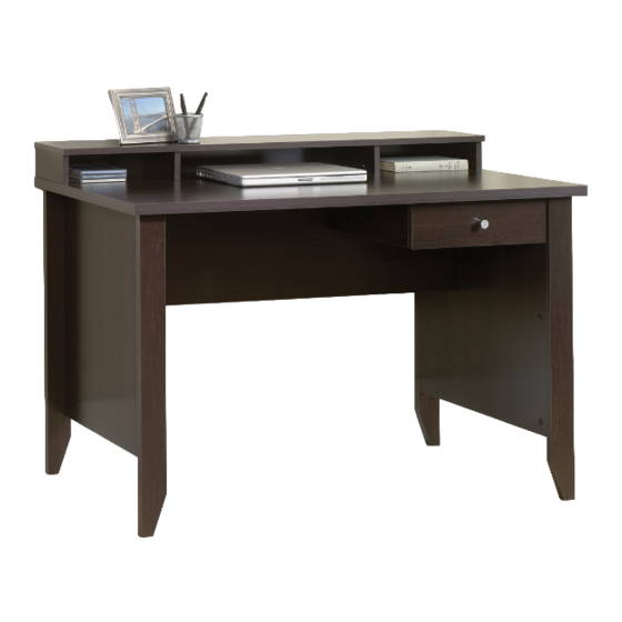
Writing Desk
418269
Need help? Visit Sauder.com to view video assembly tips or chat with a live rep.
Prefer the phone? Call 1-800-523-3987.
Share your journey!
The original desktop.
NOTE: THIS INSTRUCTION
BOOKLET CONTAINS IMPORTANT
SAFETY INFORMATION.
PLEASE READ AND KEEP FOR
FUTURE REFERENCE.
English pg 1-18
Français pg 19-21
Español pg 22-24
Lot # 369030
03/18/15
Purchased: __________________
Be sure to give us a ring before
making any returns. 1-800-523-3987
Advertisement

Related Manuals for Sauder 418269


Summary of Contents for Sauder 418269
- Page 1 Writing Desk 418269 NOTE: THIS INSTRUCTION BOOKLET CONTAINS IMPORTANT SAFETY INFORMATION. Need help? Visit Sauder.com to view video assembly tips or chat with a live rep. PLEASE READ AND KEEP FOR FUTURE REFERENCE. Prefer the phone? Call 1-800-523-3987. English pg 1-18 Français pg 19-21...
- Page 2 Assembly Tools Required Part Identifi cation No. 2 Phillips Screwdriver Tip Shown Actual Size Hardware Identifi cation Assembly Steps 5-18 Hammer Not actual size Français 19-21 Español 22-24 Skip the power trip. Safety 25-26 This time. Warranty Page 2 418269 www.sauder.com/services...
-
Page 3: Part Identification
BACK (1) RIGHT FRONT LEG (1) LEFT FRONT LEG (1) REAR LEG (2) DRAWER FRONT (1) HUTCH LEFT END (2) D20 DRAWER RIGHT SIDE (1) DRAWER LEFT SIDE (1) DRAWER BACK (1) D716 DRAWER BOTTOM (1) D716 www.sauder.com/services 418269 Page 3... -
Page 4: Hardware Identification
CAM COVER - 6 NAIL - 24 GLUE - 1 3S GOLD 5/16" FLAT HEAD SCREW - 8 BLACK 1-7/8" FLAT HEAD SCREW - 7 30S BLACK 1-9/16" FLAT HEAD SCREW - 4 BLACK 7/8" MACHINE SCREW - 1 Page 4 418269 www.sauder.com/services... - Page 5 Assemble your unit on a carpeted fl oor or on the empty å carton to avoid scratching your unit or the fl oor. To begin assembly, push a SAUDER TWIST-LOCK® å FASTENER (7F) into the large holes in the HUTCH ENDS (C and M).
- Page 6 CAM DOWELS into these edges. Arrow Arrow Insert the metal end of the CAM DOWEL into the HIDDEN CAM. Hole The arrow in the HIDDEN CAM must point toward the hole in the edge of the board. Page 6 418269 www.sauder.com/services...
- Page 7 Fasten the ENDS (A and B) to the FRONT LEGS (I and J). å Tighten six HIDDEN CAMS. (6 used) Angled edge These surfaces should be even. These surfaces should be even. Angled edge Edge with HIDDEN CAMS www.sauder.com/services 418269 Page 7...
- Page 8 Fasten the REAR LEGS (K) to the ENDS (A and B). Use six å BLACK 1-7/8" FLAT HEAD SCREWS (2S). Some assembly (and snacks) required. Angled edge BLACK 1-7/8" FLAT HEAD SCREW (6 used in this step) Page 8 418269 www.sauder.com/services...
- Page 9 CABINET LEFT (35GB) to the UPRIGHT (D). Use four GOLD 5/16" FLAT HEAD SCREWS (3S) through holes #1 and #3. GOLD 5/16" FLAT HEAD SCREW Roller end (4 used in this step) Roller end Edge and surface with HIDDEN CAMS www.sauder.com/services 418269 Page 9...
- Page 10 Tighten Risk of damage or Arrow injury. HIDDEN CAMS must be completely Arrow Maximum tightened. HIDDEN 210 degrees CAMS that are not completely tightened may loosen, and parts may separate. To Minimum completely tighten: 190 degrees Page 10 418269 www.sauder.com/services...
- Page 11 Fill the holes 1/4 to 1/2 full with GLUE. holes in the ENDS. Wipe away the excess GLUE. Caution Inspect the parts thoroughly before assembling. Disassembly of glued parts is extremely diffi cult. Place GLUE in the exact holes shown. Finished edge www.sauder.com/services 418269 Page 11...
- Page 12 BLACK 1-7/8" FLAT HEAD SCREW (2S). Minimum 190 degrees BLACK 1-7/8" FLAT HEAD SCREW (1 used in this step) i t h o f a c S u r D E N H I D Page 12 418269 www.sauder.com/services...
- Page 13 Step 9 Carefully stand your unit upright. å How to use the SAUDER TWIST-LOCK ® FASTENER Fasten the HUTCH UPRIGHTS (C and M) to the TOP (E). 1. Insert the dowel end of the FASTENER into the hole of the å...
- Page 14 BACK. Carefully cut out the holes needed. NAIL (24 used in this step) n i s h U n fi f a c s u r These holes must line up over the HUTCH UPRIGHTS (C and M). Page 14 418269 www.sauder.com/services...
- Page 15 Fasten the DRAWER BACK (D74) to the DRAWER SIDES (D20 å and D21). Use four BLACK 1-9/16" FLAT HEAD SCREWS (30S). NOTE: Be sure the DRAWER BOTTOM (D716) inserts into the å groove of the DRAWER BACK (D74). www.sauder.com/services 418269 Page 15...
- Page 16 Screw head - turn CAM to line up holes in the SLIDES with holes in DRAWER SIDES Roller end BLACK 7/8" MACHINE SCREW (1 used for the KNOB) GOLD 5/16" FLAT HEAD SCREW (4 used in this step) Page 16 418269 www.sauder.com/services...
- Page 17 Push a CAM COVER (12P) onto each visible HIDDEN CAM. å 20 lbs. 50 lbs. 10 lbs. Place the roller on the SLIDE behind the roller on the RAIL. (6 used) To cover HIDDEN CAMS www.sauder.com/services 418269 Page 17...
- Page 18 #3. The higher the screw in the oblong hole, the higher your drawer front will be. The lower the screw, the lower the drawer front. Page 18 418269 www.sauder.com/services...
-
Page 19: Liste De Pièces
élément et conserver le livret pour future référence. EXTRÉMITÉ DROITE ..........1 35GA ÉLÉMENT DROITE............1 Pour contacter Sauder EXTRÉMITÉ GAUCHE ..........1 35GB ÉLÉMENT GAUCHE ...........1 en ce qui concerne cet EXTRÉMITÉ DROITE DE SURMEUBLE ..2 35GC TIROIR DROIT ..............1 élément, faire référence... - Page 20 éviter d'endommager l'élément ou le sol. Pour commencer l'assemblage, enfoncer une FIXATION ÉTAPE 6 TWIST-LOCK® SAUDER (7F) dans les gros trous des EXTRÉMITÉS DE SURMEUBLE (C et M). Fixer le VOILE DE FOND (G) aux EXTRÉMITÉS (A et B). Serrer six EXCENTRIQUES ESCAMOTABLES.
- Page 21 COLLE. Pour insérer le tiroir dans l'élément, abaisser le devant du tiroir Utilisation de la FIXATION TWIST-LOCK® SAUDER et faire passer les roulettes situées sur le tiroir derrière les roulettes situées sur l'élément. Relever le devant du tiroir et 1.
-
Page 22: Lista De Partes
35GA GABINETE DERECHO ..........1 et conserver le livret pour future référence. EXTREMO IZQUIERDO ..........1 35GB GABINETE IZQUIERDO ...........1 Pour contacter Sauder EXTREMO DERECHO DE ORGANIZADOR ..2 35GC CAJÓN DERECHO ............1 en ce qui concerne cet PARAL ...................1 35GD CAJÓN IZQUIERDO ...........1 élément, faire référence... - Page 23 No. 1 y No. 3. Para comenzar el ensamblaje, empuje un SUJETADOR TWIST-LOCK® SAUDER (7F) dentro de los agujeros grandes de PASO 6 los EXTREMOS DE ORGANIZADOR (C y M).
- Page 24 Quite el exceso de PEGAMENTO. Para insertar el cajón dentro de la unidad, incline la parte Cómo utilizar el SUJETADOR TWIST-LOCK® SAUDER delantera del cajón hacia abajo y deje que los rodillos del cajón caigan detrás de los rodillos de la unidad. Levante la parte 1.
- Page 25 à Les téléviseurs peuvent être particulièrement un téléviseur. cet eff et. lourds. De plus, le poids et l’emplacement du tube image ont tendance à rendre les téléviseurs instables et enclins à tomber vers l’ a vant. www.sauder.com/services 418269 Page 25...
- Page 26 Además, el peso y la ubicación del tubo de imagen tienden a causar la inestabilidad de televisores y propensa a volcarse hacia adelante. Page 26 418269 www.sauder.com/services...
-
Page 27: Year Limited Warranty
GARANTIE LIMITÉE DE 5 ANS 1. Sauder Woodworking Co. (Sauder®) off re une couverture de garantie limitée à l’ a cheteur 4. La présente garantie ne s’ a pplique qu’ a ux défauts garantis qui se produisent pour initial du présent produit pendant une période de cinq ans à... - Page 28 Dear Valued Customer: So, how did it go? Thanks so much for choosing Sauder® furniture. I hope the Set a world record for speed? purchase and assembly process was a positive experience Feeling good about yourself? and you feel good about the furniture you just built. If you Nice.
Need help?
Do you have a question about the 418269 and is the answer not in the manual?
Questions and answers